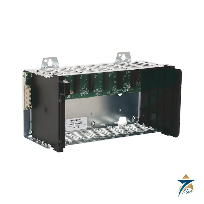
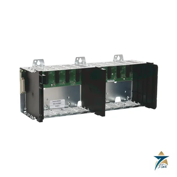
A seven-slot ControlLogix backplane
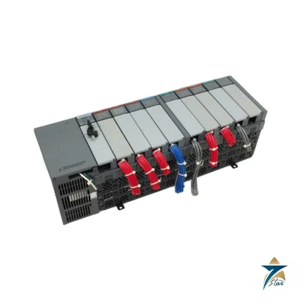
The Allen-Bradley 1756-A7 is the seven-slot member of the standard ControlLogix chassis range. It holds the controller, the network communication modules and a mix of digital, analog and specialty I/O in one rack, with a power supply fitted on the left. The backplane provides the high-speed link between modules and passes power to every slot, and Rockwell Automation states that any module can go in any slot.
With a stated weight of 1.10 kg and power dissipation of 4.5 W, it is the usual choice for a medium panel that needs a controller, a pair of communication cards and several I/O modules.
Technical specifications
| Parameter |
Specification |
| Catalog number |
1756-A7 (series B and C; 1756-A7K is the conformal-coated version) |
| Slots |
7 |
| Mounting |
Horizontal back-panel mounting only, in a panel (open-style, no enclosure rating) |
| Backplane current, chassis / slot, 1.2V DC |
1.5 A / – |
| Backplane current, chassis / slot, 3.3V DC |
4 A / 4 A |
| Backplane current, chassis / slot, 5.1V DC |
15 A / 6 A |
| Backplane current, chassis / slot, 24V DC |
2.8 A / 2.8 A |
| Power dissipation, max |
4.5 W |
| Isolation voltage |
Determined by the installed power supply and modules |
| Minimum cabinet size (H x W x D) |
50.8 x 61.0 x 20.3 cm (20 x 24 x 8 in.) |
| Weight, approx |
1.10 kg (2.4 lb) |
| Operating temperature |
Series B: 0…60 °C (32…140 °F); series C: -25…+60 °C (-13…+140 °F) |
| Non-operating temperature |
-40…+85 °C (-40…+185 °F) |
| Humidity |
5…95% noncondensing |
| Vibration / shock |
2 g at 10…500 Hz operating; 30 g operating shock |
| Earth ground wire |
Functional earth: 8.3 mm² (8 AWG); protective earth: 2.1 mm² (14 AWG) copper rated 90 °C or greater |
| Temperature codes (as printed) |
North American T5 (series B) and T4 (series C); IEC T4 |
| Certifications (as printed) |
cULus (UL files E65584 and E194810), FM Class I Division 2, CE, RCM, ATEX and IECEx Zone 2 (series C: II 3 G Ex ec IIC T4 Gc) |
Panel layout and grounding
Install the chassis horizontally on the back panel. The installation instructions give a minimum cabinet of 50.8 x 61.0 x 20.3 cm for the seven-slot size, and they list the clearances to keep around the chassis for ventilation. Ground the chassis with an 8.3 mm² (8 AWG) functional earth wire and a 2.1 mm² (14 AWG) protective earth wire.
Add up the 5.1V, 3.3V, 1.2V and 24V backplane current of each module and compare the total with the chassis limits in the table, 15 A at 5.1V and 2.8 A at 24V for the whole chassis, 6 A and 2.8 A per slot.
Variants and sizes
The A7 is listed in series B and C, as the conformal-coated 1756-A7K, and in the harsh-environment XT versions in the installation instructions. If you need fewer slots, see the four-slot 1756-A4. If you need more, the 1756-A10 offers ten slots with the same backplane current ratings.
Key features of the seven-slot chassis
- Seven module slots plus a power supply position on the left side of the chassis.
- A passive backplane that carries data between modules and distributes 1.2V, 3.3V, 5.1V and 24V DC from the power supply.
- Any module can be placed in any slot, so the controller, communication adapters and I/O can be arranged to suit wiring and panel layout.
- Series C extends the operating range down to -25 °C and carries ATEX and IECEx Zone 2 marking as printed on the documentation.
- A conformal-coated version, 1756-A7K, for atmospheres where corrosive gases or humidity are a concern.
Planning the power budget
The chassis itself does not limit the power available; the installed power supply does. Before ordering, list every module that will go in the rack and add up its current draw at each backplane voltage from its own technical data. The total must stay within the rating of the chosen 1756 power supply and within the chassis and per-slot limits given in the table above. A margin for future modules is sensible, because adding an extra I/O card later is much easier than replacing a power supply in a running panel. Where a redundant supply is needed, the redundant power supply arrangement of the ControlLogix range should be checked with the Rockwell Automation documentation.
Typical rack arrangements
| Slot use |
Example of what is fitted |
| Controller |
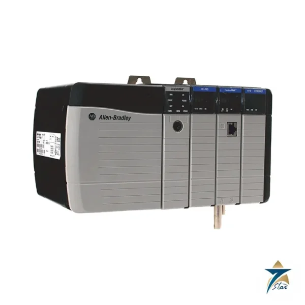
A ControlLogix controller, often in slot 0 by convention |
| Communication |
EtherNet/IP, ControlNet or DeviceNet modules for remote I/O and HMI links |
| Local I/O |
Digital, analog or specialty modules for nearby field devices |
| Spare |
Free slots kept for expansion; empty slots should be closed with a slot filler |
A seven-slot rack is also common as a remote I/O chassis with a communication adapter in place of a controller.
Installation and maintenance
- Mount on a flat, rigid back panel inside an enclosure suited to the environment, as the chassis is open-style.
- Respect the ventilation clearances from the installation instructions and keep cable ducts from blocking airflow.
- Fit slot fillers to unused slots to keep dust out of the backplane connectors.
- Follow the module instructions on removal and insertion under power before swapping cards in a live system.
- Check the earth connections during periodic panel inspections.
Use in Oman and GCC conditions
Many control panels in the region sit in field substations, pump stations and plant rooms where cooling is limited and fine dust is common. The series B rating of 0 to 60 °C and series C rating of -25 to +60 °C refer to the air around the chassis inside the enclosure, which in summer can be well above outdoor shade temperature. Size enclosure cooling or air conditioning accordingly, use filtered ventilation, and consider the conformal-coated 1756-A7K in coastal or chemical plant atmospheres where salt and corrosive gases are present.
What to include in an RFQ
Please state the catalog number and series letter required (1756-A7 series B or C, or 1756-A7K), the quantity, whether a power supply and slot fillers should be quoted with the chassis, and the modules planned for the rack so compatibility can be checked. If the chassis replaces an existing unit, a photo of the nameplate helps confirm the series.
Documents and quotation
The Rockwell Automation ControlLogix chassis installation instructions are attached; the full technical data sheet, publication 1756-TD006, is on the Rockwell Automation literature library. See our PLC and I/O cards catalogue for compatible controllers and I/O. Confirm the exact catalog number, series letter and firmware or hardware revision on the product label, and the compatibility with your existing system, before ordering. Stock and lead time are confirmed at quotation.






Reviews
There are no reviews yet.