- AC Drives
- Industrial Communications
- PLC & I/O Cards
- Vibration Monitoring
- Automation Accessories
- Controllers & Data Acquisition
- CCTV & Security
- Encoders
- Safety Switches & Guard Locking
- Industrial Computers
- HMI Displays
- Motor Soft Starters
- Isolator & Barrier
- Pneumatic Cylinders
- Servo Drives
- Automation Software
- Robotics
- Machine Vision
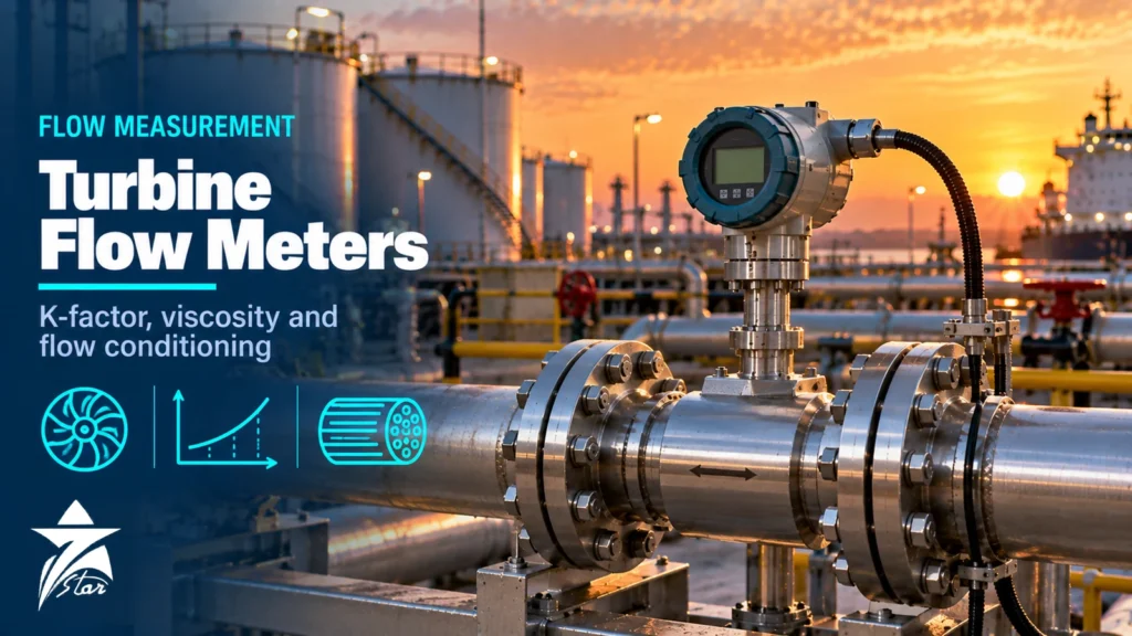
Turbine meters are among the oldest high-accuracy flow technologies still in daily use, and they remain common on refined products, crude oil loading, natural gas distribution and water. A turbine flow meter is simple in concept: the fluid spins a bladed rotor, and the rotor speed is proportional to velocity. Getting the stated accuracy in practice is another matter. The meter factor depends on viscosity, flow profile, bearing condition and installation, and a turbine that was perfect at the calibration rig can drift once it sees a different product or a swirling inlet. This guide covers liquid and gas turbine meters, the K-factor and how it is used, viscosity effects, flow conditioning, and where turbines fit in custody and fiscal service.
How a Turbine Flow Meter Works
A turbine meter has a rotor with helical blades mounted on bearings inside a flow tube. Upstream and downstream flow straighteners (often called hangers or diffusers) support the rotor shaft and reduce swirl. As fluid passes, it drives the rotor at a speed that, over the linear range, is proportional to the mean velocity.
A pickup coil or sensor in the meter body detects each blade (or a magnet or reference button on the rotor) as it passes, producing a pulse train. The pulse frequency is proportional to the volumetric flow rate, and the total pulse count is proportional to the volume passed. Common pickups include:
- Magnetic (reluctance) pickups, which need no power but add slight drag and give a low signal at low flow.
- Modulated carrier or RF pickups, which add essentially no drag and help low-flow performance.
- Dual pickups, phase-shifted so that a flow computer can check pulse integrity, as required in many custody systems.
The output is volume at flowing conditions. For liquids, a flow computer corrects to standard volume using temperature, pressure and the product’s expansion coefficients. For gas, pressure and temperature (and compressibility) corrections convert actual volume to standard volume.
Understanding the K-Factor and Meter Factor
The K-factor is the number of pulses per unit volume, for example pulses per litre or pulses per barrel. It is determined by calibration and is printed on the calibration certificate.
Two related terms are often confused:
- K-factor: pulses per unit volume, used to convert the raw pulse count into indicated volume.
- Meter factor: a dimensionless correction (close to 1.0000) found by proving the meter against a reference, such as a pipe prover, compact prover or master meter, at operating conditions. Indicated volume multiplied by the meter factor gives the corrected volume.
A turbine’s K-factor is not perfectly constant. It typically rises slightly at low and medium flows (the so-called hump) before flattening, and falls off sharply near the bottom of the range where bearing friction and fluid drag dominate. Linearity is often stated as a band around the mean K-factor across the rated range, with repeatability usually much better than linearity. Many modern flow computers apply a multi-point K-factor curve rather than a single average, which tightens accuracy across the range.
Liquid Turbine Meters
Liquid turbines are used on refined products such as gasoline, diesel, jet fuel and naphtha, on light crude, on LPG and on clean water and chemicals. The relevant industry reference for hydrocarbon liquids is API MPMS Chapter 5.3, Measurement of Liquid Hydrocarbons by Turbine Meters.
Points to check for liquid service:
- Cleanliness: turbines need clean liquid. A strainer upstream is standard; debris can damage blades and bearings.
- Cavitation: if the pressure downstream of the rotor falls below vapour pressure, flashing causes over-reading and rotor damage. Maintain adequate back pressure; manufacturers and API guidance give back-pressure rules, typically based on pressure drop across the meter and the product’s vapour pressure.
- Bearings: tungsten carbide or ceramic sleeve bearings and ball bearings are common. Bearing wear shifts the low-flow end of the curve first.
- Over-speed: a sudden flush of gas through a liquid meter, for example when filling an empty line, can spin the rotor far beyond its rating and damage it.
Gas Turbine Meters
Gas turbines are widely used on natural gas distribution, industrial supply and some transmission duties, usually at moderate to high pressure. In the gas industry, AGA Report No. 7, Measurement of Natural Gas by Turbine Meters, sets out construction, installation and calibration practice, and European practice references EN 12261.
Gas turbines differ from liquid designs in several ways:
- The driving torque is much lower because gas density is low, so rotors are lighter and the hub covers more of the bore to raise velocity at the blades.
- Rangeability improves as pressure rises, because the denser gas gives more torque at low flow.
- Many models include a lubrication system for bearings.
- Mechanical index heads with a low-frequency pulse are still common, alongside high-frequency sensors used by electronic volume correctors and flow computers.
Sudden pressurisation, liquids in the line and over-ranging during start-up are the most common causes of gas turbine damage. Slow opening of upstream valves protects the rotor.
Viscosity Effects
Viscosity is the most important limitation of a liquid turbine meter. As viscosity rises, fluid drag on the blades and hub increases, the velocity profile changes, and the K-factor shifts, particularly at the lower end of the flow range. The usable linear range shrinks as a result.
A practical way to describe this is the universal viscosity curve, which plots K-factor against flow frequency divided by kinematic viscosity (a value related to Reynolds number). Meters of the same design follow similar curves, which lets the user predict the K-factor when the product viscosity changes, and lets a flow computer compensate automatically if viscosity or temperature is measured.
For practical selection:
- Low-viscosity products such as gasoline, jet fuel, diesel and water are ideal.
- For heavier products such as heavy fuel oil, lube oils and many crudes, turbines can still be used with a viscosity-specific calibration, a helical-blade design or a larger meter running at a higher Reynolds number. Positive displacement or Coriolis meters often perform better.
- Where one meter handles several products, calibrate or prove on each product, or use a viscosity-compensated K-factor curve.
Temperature changes alter viscosity too, so an outdoor meter that sees a large daily temperature swing may need temperature-based compensation.
Flow Conditioning and Installation
A turbine responds to the velocity at the blades, so swirl and asymmetric profiles directly bias the reading. Swirl that rotates in the same direction as the rotor makes it run fast; opposing swirl makes it run slow.
- Straight run: older practice called for long upstream lengths, often quoted as 10 or more diameters with additional length after complex fittings. A flow conditioner or tube bundle allows shorter runs. AGA 7 describes recommended gas meter runs with straightening vanes; follow the manufacturer and the applicable standard.
- Downstream run: a shorter downstream section, commonly around 5 diameters, keeps the outlet stable.
- Strainer and air eliminator: on liquid service, install a strainer and, where gas or air can enter, an air eliminator upstream.
- Valves: place control valves downstream of the meter so that the meter stays full and back pressure is maintained.
- Electrical: route pickup cables away from motors and power cables; use shielded twisted pair and ground the shield at one end.
- Orientation: most turbines are designed for horizontal installation; vertical mounting may change the calibration and should be confirmed with the manufacturer.
Turbine Meter Types Compared
| Design | Typical service | Strengths | Limitations |
|---|---|---|---|
| Conventional axial liquid turbine | Refined products, water, light chemicals | High repeatability, compact, cost-effective | Sensitive to viscosity and swirl; needs clean liquid |
| Helical or dual-rotor liquid turbine | Crude oil, products with wider viscosity range | Wider viscosity tolerance; dual rotor reduces swirl effects | Higher cost and complexity |
| Gas turbine (axial) | Natural gas distribution and industrial supply | Good accuracy at pressure, widely standardised | Damage risk from over-speed and liquids; bearing maintenance |
| Insertion turbine | Large pipes, utility and HVAC monitoring | Low cost on big lines, hot-tap options | Point velocity only; lower accuracy |
Custody Transfer and Fiscal Use
Turbines are long-established in custody metering of refined products and light crude, especially at truck and marine loading terminals and on pipelines. A typical custody liquid skid places turbine meters in parallel streams with strainers, temperature and pressure transmitters, a flow computer and a connection to a prover so that each meter can be proven on product at operating conditions. Pulse fidelity checks with dual pickups, as described in API MPMS Chapter 5.5, help to detect lost or added pulses.
For gas, turbines are used for fiscal and sales measurement where the national metrology rules permit, often with an electronic volume corrector or flow computer. In larger transmission stations, multipath ultrasonic meters have taken much of the market, but turbines remain common at smaller stations and in distribution.
For the wider design of these systems, see our custody transfer metering system guide and the comparison of flow computers for metering stations. Flow computers themselves are listed in our flow computers category.
Maintenance and Troubleshooting
- Rising K-factor at low flow, falling elsewhere: suspect bearing wear or a damaged blade.
- Erratic or missing pulses: check pickup gap, cable shielding and the flow computer’s pulse input settings.
- Reading high after a line fill: possible over-speed damage or gas in the liquid.
- Gradual meter factor drift during proving: track it on a control chart; a trend usually signals wear or deposits before they become large errors.
- Strainer differential pressure: monitor it, because a blocked strainer can cause cavitation at the meter.
A documented proving and verification routine, as covered in our instrument calibration program guide, keeps turbine performance visible over time.
Turbine Flow Meter Selection Checklist
- Fluid, with viscosity range across all operating temperatures
- Minimum, normal and maximum flow, and required linear range
- Operating and design pressure and temperature
- Vapour pressure (liquids) and required back pressure
- Cleanliness, strainer mesh and any air or gas entrainment
- Available straight run and choice of flow conditioner
- Pickup type, dual pickups for pulse security and output signals
- Custody or fiscal requirements, applicable standards and proving method
- Hazardous area classification of the meter and pickups
- Materials for bearings, rotor and body compatible with the product
Turbine Meters and Flow Computers We Supply
A K-factor is only as good as the meter that produces it and the electronics that apply it. These examples cover small and large liquid turbines and the flow computers that turn pulses into corrected volume.
| Product | Type | Where it fits |
|---|---|---|
| Titan Enterprises 800 Series Turbine Flow Meter | Small turbine flow meter | Low flows of clean, low-viscosity liquids. |
| Tecfluid TM Series Turbine Flowmeter for Liquids | Turbine flowmeter for liquids | General clean-liquid metering and batching. |
| Cameron NuFlo FE-1000E/FE-1000F Liquid Turbine Flowmeter Assembly, 3-inch ANSI 150# | Liquid turbine flowmeter | Produced water and liquid hydrocarbon measurement in the oilfield. |
| Cameron NuFlo 1502 WECO Union High-Pressure Liquid Turbine Flowmeter | High-pressure liquid turbine | Injection and high-pressure lines with hammer-union connections. |
| Faure Herman Heliflu-TZN Helical Turbine Flowmeter | Helical turbine flowmeter | Custody transfer of liquid hydrocarbons, including more viscous products. |
| Cameron NuFlo Scanner 2000 microEFM Flow Computer | Flow computer | Totalising and correcting turbine pulses at remote wellsites. |
| FloBoss S600+ Flow Computer | Emerson Custody Transfer & Fiscal Measurement | Flow computer | Custody transfer metering stations with meter proving and K-factor linearisation. |
For a replacement meter or rotor kit, send the meter size, model and serial number and the current K-factor from the calibration certificate through our quote request form.
Sourcing Turbine Flow Meters Through Seven Star LLC
Seven Star LLC supplies liquid and gas turbine meters, pickups, preamplifiers, flow conditioners and spare rotor kits on request, from manufacturers such as Emerson (Daniel), Honeywell (Elster), Itron, Badger Meter and Hoffer. Browse the flowmeters category for typical models. We help with selection and with cross-checking part numbers against nameplates and calibration certificates; availability and lead time are confirmed at quotation.
Send us the meter nameplate, calibration certificate or your RFQ with product, viscosity, flow range and pressure, and we will return a matched quotation.
Frequently asked questions
What is the K-factor of a turbine flow meter?
The K-factor is the number of pulses the meter produces per unit volume, such as pulses per litre or per barrel. It is determined by calibration and appears on the calibration certificate. The flow computer divides the pulse count by the K-factor to obtain indicated volume.
What is the difference between K-factor and meter factor?
The K-factor converts pulses to indicated volume. The meter factor is a dimensionless correction close to 1.0000, found by proving the meter against a reference at operating conditions. Multiplying indicated volume by the meter factor gives corrected volume.
Can a turbine meter measure heavy oil?
It can with limits. Higher viscosity shifts the K-factor and narrows the linear range, especially at low flow. Viscosity-specific calibration, helical-rotor designs or a different technology such as positive displacement or Coriolis are usually considered for heavy products.
How much straight pipe does a turbine meter need?
Turbines are sensitive to swirl, so long upstream runs are traditional, often quoted as 10 diameters or more, with about 5 diameters downstream. A flow conditioner or straightening vanes allows shorter runs. Follow the manufacturer's manual and the applicable standard, such as AGA Report No. 7 for gas.
Why do turbine meters fail after a line fill?
When an empty or partly filled liquid line is filled quickly, air or gas pushed through the meter can spin the rotor far above its rated speed. This over-speed can damage bearings and blades. Filling slowly and venting the line protects the meter.
Are turbine meters still used for custody transfer?
Yes, especially for refined products and light crude at loading terminals and pipelines, where they are proven against a prover at operating conditions. For gas, they remain common at smaller stations, while multipath ultrasonic meters are widely used in large transmission stations.
Was this guide helpful?One click helps us write better guides for engineers.
Thank you! Glad it helped. Need this equipment for your project? Request a quotation
Thank you. We will use this to improve the guide.