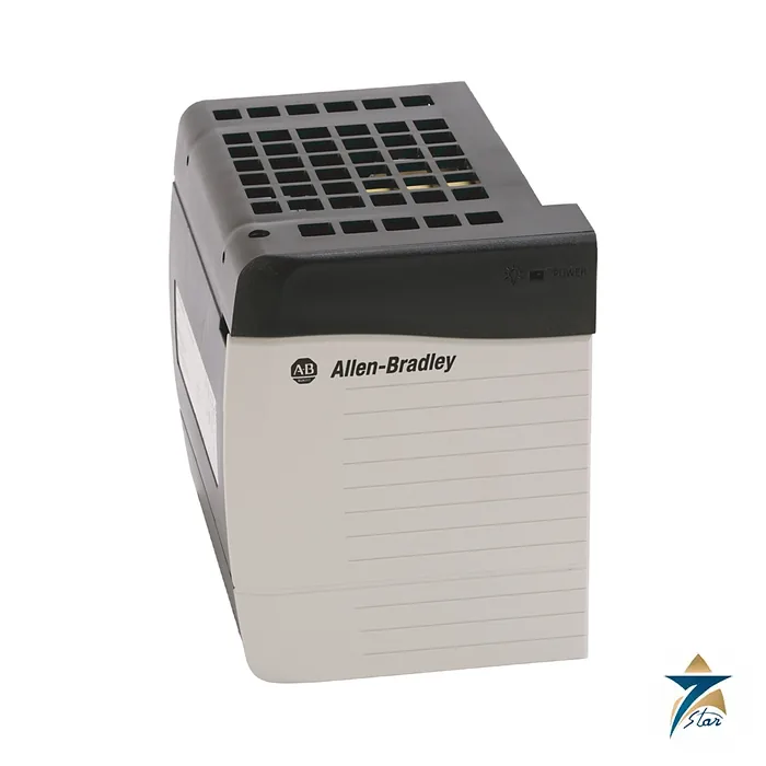
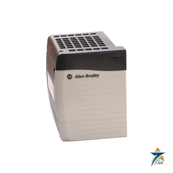
A 75 W AC supply for the ControlLogix chassis
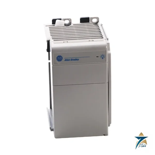
The Allen-Bradley 1756-PA75 is a standard AC power supply for the ControlLogix chassis. It mounts at the left side of a 1756-A4, A7, A10, A13 or A17 chassis, accepts 85 to 265V AC at 47 to 63 Hz, and delivers up to 75 W of total output across the backplane rails. The 5.1V rail is rated 13 A, the 3.3V rail 4 A, the 1.2V rail 1.5 A and the 24V rail 2.8 A.
Compared with the 10 A at 5.1V of the 1756-PA72, the PA75 offers more current on the logic rail, which matters when the chassis carries controllers, communication modules and heavily loaded I/O cards.
Technical specifications
| Parameter |
Specification |
| Catalog number |
1756-PA75 (series B; 1756-PA75K is the conformal-coated version) |
| Type |
ControlLogix standard AC power supply, fits at the left side of the chassis |
| Input voltage range |
85…265V AC, nominal 120V/240V AC; 47…63 Hz |
| Input power, max |
100 VA / 100 W |
| Output power, max |
75 W at 0…60 °C (32…140 °F), total of all backplane outputs |
| Current capacity at 1.2V DC |
1.5 A |
| Current capacity at 3.3V DC |
4 A |
| Current capacity at 5.1V DC |
13 A |
| Current capacity at 24V DC |
2.8 A |
| Hold-up time |
2 cycles at 85V AC, 60 Hz; 6 cycles at 120V AC, 60 Hz; 20 cycles at 220V AC, 60 Hz |
| Isolation voltage |
250V continuous, reinforced insulation, power input to backplane; type tested at 3500V DC for 60 s |
| Dimensions (H x W x D), approx |
14.0 x 11.2 x 14.5 cm (5.51 x 4.41 x 5.71 in.) |
| Chassis |
1756-A4, A7, A10, A13 and A17; chassis series B and C |
| Wire size |
2.5 mm² (14 AWG) solid or stranded copper rated at 90 °C (194 °F) or greater, 1.2 mm insulation maximum |
| Conductor screw torque |
0.565 N•m (5 lb•in) |
| Operating temperature |
0…60 °C (32…140 °F) |
| North American temperature code (as printed) |
T4 |
| Enclosure type rating |
None (open-style) |
Sizing the supply
The total output of all four backplane rails together cannot exceed 75 W. Add the 5.1V and 24V currents of each module in the chassis, using the module data sheets, and check each rail against its limit. Maximum input power is 100 VA, so size the upstream protection and cabling for that figure.
Wiring is by screw terminals for 2.5 mm² (14 AWG) copper rated at 90 °C or greater, tightened to 0.565 N•m. The supply has no enclosure rating and must be installed in a suitable panel. Hold-up time is stated as 2 cycles at 85V AC, 6 cycles at 120V AC and 20 cycles at 220V AC with a 60 Hz supply.
Compatibility and variants
The data sheet lists the PA75 as series B and compatible with chassis series B and C. The 1756-PA75K is the conformal-coated version of the same supply. Redundant supply versions are separate catalog numbers. Confirm the input type before ordering.
Installing the 1756-PA75 in a control panel
The supply occupies the left-hand position of the ControlLogix chassis, so plan the panel layout with that side accessible for the incoming AC wiring and for removal of the supply in future. Isolate the incoming feed before fitting or removing the unit, seat it squarely against the chassis, and tighten the fixing screws so the backplane connection is firm. Route the AC conductors away from low-level signal and network cables, and provide a dedicated, clearly labelled disconnect and protective device upstream so that maintenance staff can isolate the rack without affecting other loads in the panel.
A sound protective earth is essential. Bond the chassis and the panel back plate according to the Rockwell Automation grounding guidelines and the local wiring regulations, and keep the earth path short and free of paint at the contact points. Poor earthing is a common cause of intermittent communication faults that are later blamed on modules rather than on the installation.
Commissioning checks before energising the rack
Before the first power-up, measure the incoming voltage at the terminals and confirm that it lies within the input range shown in the specification table. Recheck the terminal screws, confirm that the conductor size and insulation match the wiring requirements, and verify that the sizing calculation for all four backplane rails has been recorded for the as-built module arrangement. When power is applied, watch the controller and module status indications for normal start-up behaviour and record the result in the commissioning sheet.
If the chassis will later receive more modules, repeat the power budget check at that stage. A rack that was well within limits at handover can approach the 75 W total once extra communication or I/O cards are added during plant extensions.
Heat, dust and humidity in GCC panels
The rated output is stated for an ambient of 0 to 60 °C, and that figure refers to the air around the supply inside the enclosure, not the outdoor shade temperature. In Oman and the wider Gulf, panels installed in field shelters, rooftop rooms or substations can run much hotter internally than the control room, especially during summer afternoons. Check the real enclosure temperature with a logger during the hottest period, keep the ventilation spaces around the chassis clear, and consider panel cooling where internal temperatures approach the limit.
Fine sand and dust drawn in by fans can settle on the supply and the backplane, so use filtered ventilation and replace the filter media on a regular schedule. In coastal and humid sites, condensation and salt-laden air are the main concerns; this is where the conformal-coated 1756-PA75K mentioned above is often evaluated, and panel heaters or sealed, air-conditioned enclosures help keep moisture away from the electronics.
Maintenance routine
During planned shutdowns, inspect the terminals for discolouration or looseness, clean dust from the panel with a suitable vacuum rather than compressed air, and review any controller fault logs for power-related events. Keeping a record of these inspections makes it easier to spot gradual problems with the supply or the upstream feed.
Documents and quotation
The Rockwell Automation ControlLogix power supply installation instructions are attached; the technical data sheet, publication 1756-TD005, is on the Rockwell Automation literature library. See our PLC and I/O cards catalogue for chassis and modules. Confirm the exact catalog number, series letter and firmware or hardware revision on the product label, and the compatibility with your existing system, before ordering. Stock and lead time are confirmed at quotation.




Reviews
There are no reviews yet.