Two 4-20 mA outputs on a single POINT I/O slot
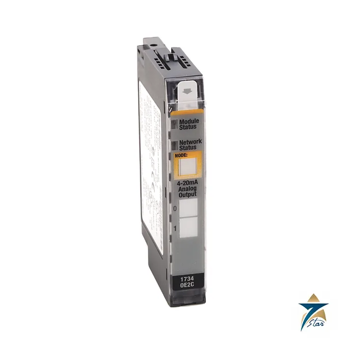
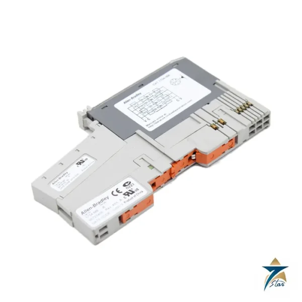
The Allen-Bradley 1734-OE2C is a POINT I/O analog output module with two current outputs. Each channel can be configured for 4 to 20 mA or 0 to 20 mA and drives loads such as valve positioners, current-to-pneumatic converters, chart recorders and variable-speed drive references. The module outputs 0 mA until communication has been established, which is a safe default for most loops.
It shares a housing with the voltage version, 1734-OE2V, and the installation sheet covers both. This page concerns the current version only; the C in the catalog number identifies current.
Technical specifications
| Parameter |
Specification |
| Manufacturer / family |
Allen-Bradley (Rockwell Automation) / POINT I/O |
| Catalog number |
1734-OE2C (1734-OE2CK is the coated version) |
| Outputs |
2 single-ended, non-isolated, current |
| Output current range |
4 to 20 mA or 0 to 20 mA, user configurable |
| Resolution |
13 bits over 0 to 21 mA, 2.5 uA per count average |
| Absolute accuracy |
0.1% of full scale at 25 °C |
| Accuracy drift with temperature |
30 ppm per C |
| Resistive load on current output |
0 to 750 ohm |
| Conversion rate / step response |
16 us / 24 us to 63% of full scale |
| Data format |
Signed integer |
| External DC power |
24V DC nominal, 10 to 28.8V DC, 70 mA including outputs at 20 mA |
| POINTBus current, max |
75 mA at 5V DC |
| Keyswitch position |
4 |
| Dimensions (H x W x D) / weight |
56.6 x 12.1 x 77.5 mm / 36 g |
| Terminal bases |
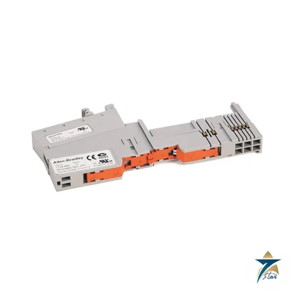
1734-TB, 1734-TBS, 1734-TOP, 1734-TOPS and the 3-wire versions |
Performance that matters when you size the loop
The sheet lists a resolution of 13 bits over 0 to 21 mA, around 2.5 microamps per count, an absolute accuracy of 0.1% of full scale at 25 °C and a drift of 30 ppm per degree Celsius. Conversion is by digital-to-analog converter at 16 microseconds, with a 24 microsecond step response to 63% of full scale.
The compliance of each channel covers loads from 0 to 750 ohm. Add up the loop resistance of the field cable and the receiving device before choosing it for a long run. The outputs are single-ended and non-isolated from each other, so do not use them where independent isolation between channels is required.
Power, mounting and keying
The module needs external 24V DC field power (10 to 28.8V DC range) with a supply current of 70 mA including both outputs at 20 mA, plus 75 mA from POINTBus at 5V DC. Power dissipation is 1.23 W with 750 ohm loads and 1.83 W with 0 ohm loads. It mounts on a 1734-TB, 1734-TBS, 1734-TOP or 1734-TOPS family base, with the keyswitch set to position 4.
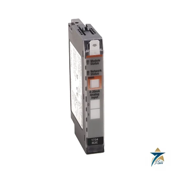
Wire with shielded copper, 22 to 14 AWG, rated at 75 °C or higher. The status indicators show module, network and output status for each channel. The family is certified for Class I Division 2 and for Zone 2 ATEX and IECEx as listed in the sheet; confirm the marks on the module you receive.
Key features of the 1734-OE2C
- Two current output channels, each configurable for 4–20 mA or 0–20 mA.
- 13-bit resolution over 0–21 mA and 0.1 % of full scale absolute accuracy at 25 °C.
- Loads up to 750 ohm per channel.
- Fast 16 µs conversion for responsive control loops.
- Outputs held at 0 mA until communication is established.
- Narrow 12.1 mm module on removable POINT I/O terminal bases.
Checking the load and loop resistance
The module can drive a total loop resistance of up to 750 ohm. This includes the input resistance of the receiving device and the resistance of both cable conductors. For a long cable run to a valve positioner or a remote indicator, add up the device input resistance, the cable resistance and any barriers or isolators in the loop. If the total exceeds 750 ohm, the output will not reach 20 mA. Note that the outputs are non-isolated; where the receiving devices are on different earths, a signal isolator may be needed.
Fault and idle behaviour
In POINT I/O, the behaviour of outputs on communication fault or program mode is configured in the module properties in the controller project. Decide whether each channel should hold its last value or go to a defined safe value, and document this in the control philosophy, especially for valves and drive references.
Building a POINT I/O node
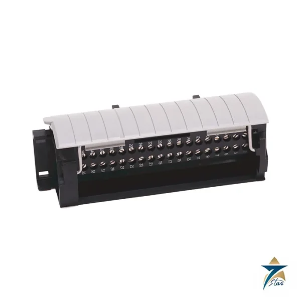
The module is installed on a terminal base on DIN rail, next to the communication adapter (for example an EtherNet/IP or DeviceNet adapter) and other POINT I/O modules. The 24 V DC field power is distributed along the backplane, and the POINTBus current (75 mA for this module) must be included in the adapter’s current budget. The mechanical keyswitch on the base should be set to position 4 so that only an appropriate module can be fitted.
Use in Oman and GCC plants
Typical applications are oil and gas skids, water treatment and HVAC systems where a PLC sends setpoints to control valves and drives. For panels exposed to humidity, salty coastal air or corrosive gases, the conformal coated version 1734-OE2CK is worth considering. Keep the panel temperature within the Rockwell specification by providing ventilation or cooling where needed.
What to include in your RFQ
State the catalog number 1734-OE2C (or 1734-OE2CK for the coated version), the quantity, and any terminal bases you need such as 1734-TB or 1734-TOP. Also give the delivery location and the required date.
Commissioning checklist
Before handing over the loop, force each channel to 4, 12 and 20 mA from the controller and measure the current with a calibrated meter at the field device. Confirm that the valve or drive responds over its full range, and record the results in the loop check sheet.
Documents and quotation
The manufacturer installation sheet 1734-IN002 gives the output table, wiring diagram and certification page. For a quotation, send the 1734-OE2C reference, series, quantity, the controller or adapter and the loads on each channel. See PLC & I/O Cards for related hardware.






Reviews
There are no reviews yet.