- AC Drives
- Industrial Communications
- PLC & I/O Cards
- Vibration Monitoring
- Automation Accessories
- Controllers & Data Acquisition
- CCTV & Security
- Safety Switches & Guard Locking
- Encoders
- Industrial Computers
- Servo Drives
- HMI Displays
- Motor Soft Starters
- Isolator & Barrier
- Pneumatic Cylinders
- Automation Software
- Machine Vision
- Robotics
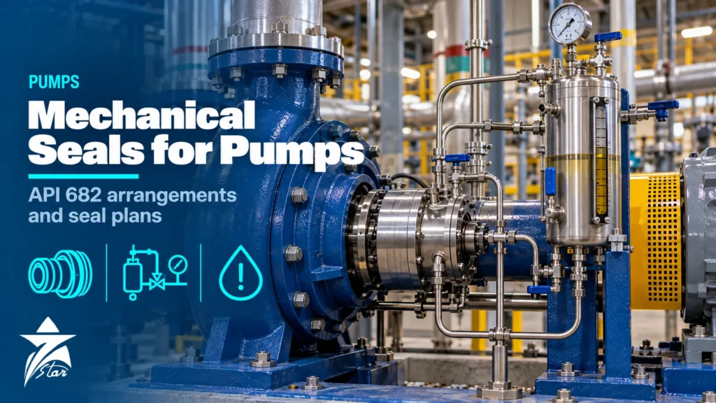
On most process pumps the mechanical seal is the component that decides the mean time between repairs. When a seal leaks, the pump is down, the area may need gas testing and the root cause is often outside the seal itself. Mechanical seals for pumps in refineries, gas plants and petrochemical units are usually specified to API 682, which brings a common language of categories, arrangements, seal types and piping plans. This guide explains that language, how to choose a seal plan for a given liquid, what a seal failure is trying to tell you and what information to collect when ordering a replacement or upgrade.
How Mechanical Seals for Pumps Work
A mechanical seal replaces packing with two flat, lapped faces: one rotating with the shaft and one stationary in the gland. Springs or a metal bellows hold the faces together, and process pressure adds closing force. A very thin fluid film between the faces carries the load and lubricates them; a small amount of vapour or liquid crosses the faces to atmosphere or to a buffer fluid. Secondary seals (O-rings, flexible graphite or other gaskets) seal the faces to the shaft sleeve and gland.
Everything that disturbs that film shortens seal life: running dry, flashing of the liquid between the faces, solids entering the gap, excessive heat, shaft movement and vibration. Seal selection is therefore mostly about controlling the environment around the faces, which is exactly what API 682 piping plans do.
API 682 in Brief
API Standard 682, “Pumps—Shaft Sealing Systems for Centrifugal and Rotary Pumps”, is the reference specification for seals in petroleum, natural gas and chemical service. The fourth edition, published in 2014, is the edition most current project specifications call up, and it is also issued as ISO 21049. It covers shaft sizes from 20 mm to 110 mm and is built around qualified, cartridge-mounted seal designs with a target of three years of continuous service. A seal is described by four choices: category, arrangement, type and piping plan.
Seal Categories 1, 2 and 3
Categories define the pump type the seal is designed for, the operating window and the depth of testing and documentation.
| Category | Intended pump | Typical operating window | Key features |
|---|---|---|---|
| Category 1 | Non-API 610 pumps (for example ISO 3069 / ASME B73 chemical pumps) | About −40 °C to 260 °C; up to about 22 bar(g) seal chamber pressure | Lighter design, fewer mandatory features, less documentation |
| Category 2 | API 610 pumps | About −40 °C to 400 °C; higher pressure limit than Category 1 (edition-dependent) | Fits API 610 seal chambers; throttle bushing requirements; qualification tested |
| Category 3 | API 610 pumps in the most demanding duties | Same window as Category 2 | Most rigorous qualification testing and documentation; distributed flush and floating throttle bushing for single seals |
Pressure limits differ between editions and manufacturers’ qualified designs, so confirm them on the seal data sheet rather than relying on a generic figure. For a refinery or gas plant API 610 pump, Category 2 is a common default; Category 3 is chosen where the end user wants full qualification test evidence and documentation.
Arrangements and Seal Types
Arrangements 1, 2 and 3
- Arrangement 1: a single seal per cartridge. Process liquid lubricates the faces, and any leakage goes to atmosphere or to a quench/drain area. Suitable for non-hazardous or low-hazard liquids with good lubricity.
- Arrangement 2: two seals in series with a buffer fluid, or a dry containment seal, between them at a pressure lower than the seal chamber. The inner seal still runs on process liquid. If the inner seal fails, the outer seal contains the leakage while it is detected and routed to a vent or flare.
- Arrangement 3: two seals with a barrier fluid between them held at a pressure higher than the seal chamber. Inner face leakage is clean barrier fluid flowing into the process, so the process never reaches atmosphere under normal operation. Used for toxic, very hazardous, poorly lubricating or solids-laden services.
Seal Types A, B and C
Type A is a balanced, rotating, multiple-spring pusher seal with elastomer O-rings, the default for most services. Type B is a rotating metal bellows seal with O-ring secondary seals, useful where a pusher might hang up from deposits. Type C is a stationary metal bellows seal with flexible graphite secondary seals for high temperatures beyond elastomer limits, such as hot hydrocarbons and heavy residues. Within each type, face materials matter: the common default is carbon against silicon carbide, while abrasive services usually move to hard-against-hard faces such as silicon carbide against silicon carbide.
Seal Piping Plans: What Each One Does
The piping plan defines how the seal chamber or the space between dual seals is supplied, cooled, vented or drained. The table below lists the plans most often seen on process pumps in the region.
| Plan | What it does | Typical use |
|---|---|---|
| 11 | Recirculation from pump discharge through an orifice into the seal chamber | Default for clean, cool liquids with Arrangement 1 |
| 13 | Recirculation from the seal chamber back to pump suction | Vertical pumps and services where venting the seal chamber is needed |
| 21 | Plan 11 flow passed through a cooler | Hot liquids where cooling the faces improves vapour margin |
| 23 | Closed loop driven by a pumping ring through a cooler | Hot water and boiler feed; efficient because only seal chamber liquid is cooled |
| 32 | Clean external flush injected into the seal chamber | Dirty, abrasive or polymerising process liquids |
| 52 | Unpressurised buffer liquid reservoir between dual seals, vented to a collection system | Arrangement 2 on flashing hydrocarbons and light ends |
| 53A/B/C | Pressurised barrier liquid via nitrogen-blanketed reservoir, bladder accumulator or piston accumulator | Arrangement 3 for toxic, hazardous or dirty services |
| 54 | Barrier liquid circulated from an external pressurised system | Arrangement 3 where several pumps share a barrier unit |
| 62 | External quench (steam, water or nitrogen) on the atmospheric side | Prevents coking, crystallisation or icing outside the faces |
| 65A/B | Leakage detection on the atmospheric side drain | Alarm on excessive leakage of Arrangement 1 seals |
| 72 / 75 / 76 | Buffer gas to a containment seal; drain of condensing leakage; vent of non-condensing leakage | Arrangement 2 with dry containment seal |
| 74 | Pressurised barrier gas to dual gas seals | Arrangement 3 non-contacting gas seals |
Choosing a Plan for the Liquid
- Clean, cool, non-hazardous: Arrangement 1 with Plan 11 is usually adequate.
- Hot liquid near its boiling point: add cooling (Plan 21 or 23) so the liquid in the seal chamber has enough margin between its pressure and its vapour pressure at the faces.
- Solids or crystallising liquids: Plan 32 with a clean compatible flush, or Plan 32 combined with a quench (Plan 62).
- Flashing hydrocarbons such as LPG and NGL: commonly Arrangement 2 with Plan 52 or Plan 72/76, the leakage path leading to a closed vent.
- Toxic or H2S-bearing liquids: Arrangement 3 with Plan 53A/B/C or 54, so leakage to atmosphere is barrier fluid, not process.
Pressurised barrier systems must be kept above seal chamber pressure; API 682 sets a minimum differential, commonly cited as 1.4 bar (20 psi), and many users run higher. Reservoir level and pressure are the main health indicators, so reliable level instrumentation and pressure transmitters or switches on the seal pot are not optional extras.
Reading a Seal Failure
A failed seal is evidence. Before discarding it, inspect the faces, secondary seals, springs or bellows and the sleeve, and record operating data from the days before the leak. Common patterns:
- Heat checking (radial cracks) on the hard face: inadequate cooling or lubrication, dry running, or a blocked flush orifice.
- Chipped face edges: vapour flashing between the faces causing face separation (popping), or excessive shaft movement.
- Wide or uneven wear track: misalignment, a bent shaft, excessive runout or pipe strain distorting the casing.
- Hard deposits on the atmospheric side: crystallisation or coking of leakage; consider a quench.
- Swollen, hardened or blistered O-rings: chemical incompatibility, excessive temperature or explosive decompression in gas-saturated service.
- Hang-up of a pusher seal: deposits on the sleeve preventing the dynamic O-ring from sliding as the face wears.
- Abrasive grooving: solids in the flush; check the cyclone separator or move to an external flush.
Many seals fail because of the pump rather than the seal: running far from BEP, cavitation, worn bearings, coupling misalignment and soft foot. Trending bearing vibration with a suitable vibration monitoring system often reveals the mechanical cause before the next seal goes.
Installation Practice
- Confirm that the cartridge part number, setting dimension and drawing match the pump and its seal chamber dimensions.
- Check shaft runout, axial float and seal chamber face squareness against the seal manufacturer’s limits before fitting.
- Keep the faces clean; do not separate cartridge components unless the instructions allow it.
- Remove the setting clips or spacers only after the gland is tightened and the drive collar is locked, and keep them for the next removal.
- Connect the piping plan exactly as drawn; check orifice size, cooler orientation and that vent points are at high points.
- Fill, vent and pressurise dual seal systems before starting the pump, and never start a pump with a dry seal chamber.
Operating and Maintaining Seal Support Systems
Seal support systems need routine attention. Check barrier and buffer reservoir levels and pressures every shift, record top-up frequency (a rising top-up rate is an early warning) and confirm the cooler is not fouled. Plan 11 and Plan 21 orifices can block with scale or polymer; a temperature rise on the flush line is a sign. Plan 53B bladder accumulators need the pre-charge pressure checked according to the manufacturer’s procedure, and the bladder replaced when it loses charge. Barrier fluid must be compatible with the process and the elastomers and have suitable viscosity across the expected temperature range.
Seals in GCC Service Conditions
High ambient temperature and solar load reduce the cooling capacity of air-cooled seal pots and finned coolers, so check the heat balance at a summer design ambient around 50 °C rather than at a standard rating condition. Sour liquids with H2S favour dual seals with a pressurised barrier, together with metallurgy and elastomers that meet NACE MR0175 / ISO 15156 where required. Seawater and produced water attack some metals and carry fine sand, which pushes the choice toward hard face pairs and corrosion-resistant metallurgy. Dusty sites need effective bearing protection on the pump, because contaminated bearings lead to vibration that ends up at the seal faces.
Data to Collect When Ordering a Seal
- Pump make, model, size and serial number, plus seal chamber dimensions or the pump’s API 610 data sheet.
- Existing seal drawing number, cartridge part number and piping plan.
- Liquid, temperature, specific gravity, vapour pressure at seal chamber temperature, solids content and any H2S or chlorides.
- Seal chamber pressure (not just discharge pressure), shaft speed and shaft diameter.
- Required category, arrangement, type and plan, and the API 682 edition named in the project specification.
- Failure history and photos of the failed faces if this is a reliability upgrade.
Mechanical Seals for Pumps: Ordering Checklist
- Category, arrangement, type and piping plan defined and matched to the liquid hazard and properties.
- Vapour margin at the faces checked at maximum temperature.
- Face and elastomer materials suitable for chemistry, temperature and solids.
- Barrier or buffer system instruments specified, with alarms connected to the control system.
- Pump operating near BEP, aligned, with acceptable vibration.
- Spare cartridge kit and installation instructions available before the planned overhaul.
Mechanical Seals We Supply
These cartridge and component seals, and the barrier fluid, cover the arrangements and piping plans described above.
| Product | Type | Where it fits |
|---|---|---|
| Flowserve ISC2 API 682 Cartridge Mechanical Seal | API 682 cartridge seal | Refinery and petrochemical pumps built to API 610. |
| EagleBurgmann Cartex-SN Single Cartridge Mechanical Seal | Single cartridge seal | General process pumps with a simple flush plan. |
| EagleBurgmann Cartex-DN Dual Cartridge Mechanical Seal | Dual cartridge seal | Toxic or hazardous liquids sealed with a pressurised barrier fluid. |
| EagleBurgmann MFL85N Metal Bellows Mechanical Seal | Metal bellows seal | High temperature service. |
| EagleBurgmann HRGS-D Gas-Lubricated Double Cartridge Seal | Gas-lubricated double cartridge seal | Pumps where a nitrogen barrier replaces liquid barrier fluid. |
| Flowserve DS-4614-5-F DuraClear Barrier Fluid | Seal barrier fluid | Filling and topping up dual seal reservoirs. |
For a replacement seal, send the seal drawing or reference, the pump model and the shaft size. For a new application, send the fluid, temperature, pressure and the piping plan through our quote request form.
Sourcing Mechanical Seals Through Seven Star LLC
Seven Star LLC supplies mechanical seals, seal support components and pump spare parts on request, together with the wider range of motors, pumps and turbines used in Oman and the GCC. We help with selection and with cross-checking seal drawing and cartridge part numbers against your pump records; availability and lead time are confirmed at quotation.
Send the seal drawing number, pump nameplate photo or your RFQ with the liquid data, and we will return matching options for your review.
Frequently asked questions
What is the difference between API 682 Arrangement 2 and Arrangement 3?
Both use two seals per cartridge. In Arrangement 2 the fluid between the seals is a buffer at lower pressure than the seal chamber, so the inner seal is lubricated by the process. In Arrangement 3 the barrier fluid is held above seal chamber pressure, so any inner seal leakage is barrier fluid going into the process.
Which API 682 seal category should I specify?
Category 1 is intended for non-API 610 chemical pumps and a narrower operating window. Category 2 suits API 610 pumps and higher temperatures. Category 3 has the same window as Category 2 but the most rigorous qualification testing and documentation, and is chosen when the owner wants that evidence.
What does Plan 53A, 53B and 53C mean?
All three are pressurised barrier liquid plans for Arrangement 3. Plan 53A uses a reservoir pressurised by nitrogen, 53B uses a bladder accumulator that separates gas from liquid, and 53C uses a piston accumulator that references seal chamber pressure. They differ in how barrier pressure is maintained and monitored.
Why do mechanical seals fail early?
The most common causes are dry running, vapour flashing between the faces, solids in the flush, misalignment and vibration from the pump, and incompatible elastomers. Inspect the faces and O-rings before discarding a failed seal, because the wear pattern usually points to the cause.
When should a quench (Plan 62) be used?
Use a quench where liquid leaking across the faces would crystallise, coke, oxidise or freeze on the atmospheric side and interfere with the seal. Steam is common for hot hydrocarbons, water for crystallising liquids and nitrogen where oxidation or moisture must be avoided.
What information is needed to replace a pump seal?
Provide the pump make, model and serial number, the existing seal drawing or cartridge part number, the piping plan, the liquid properties, seal chamber pressure, shaft speed and diameter. Photos of the failed faces help identify whether an upgrade is needed rather than a like-for-like replacement.
Was this guide helpful?One click helps us write better guides for engineers.
Thank you! Glad it helped. Need this equipment for your project? Request a quotation
Thank you. We will use this to improve the guide.