- AC Drives
- Industrial Communications
- PLC & I/O Cards
- Vibration Monitoring
- Automation Accessories
- Controllers & Data Acquisition
- Safety Switches & Guard Locking
- CCTV & Security
- Encoders
- Industrial Computers
- HMI Displays
- Motor Soft Starters
- Isolator & Barrier
- Pneumatic Cylinders
- Servo Drives
- Automation Software
- Robotics
- Machine Vision
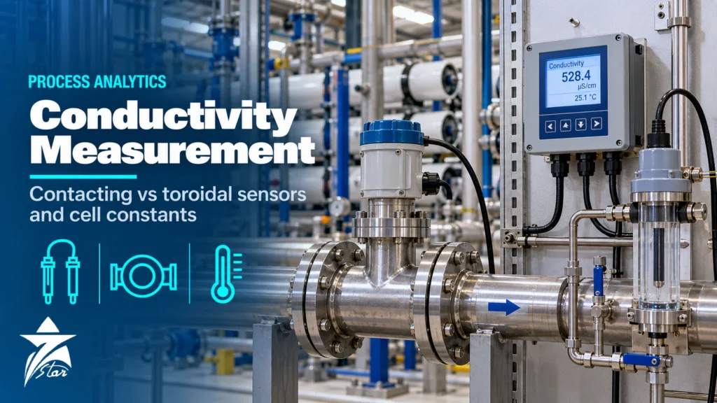
Conductivity is the cheapest and most widely used liquid analysis in a plant, yet it is routinely misapplied. A sensor that is perfect for RO permeate gives nonsense in seawater, and a sensor that survives caustic cleaning will not resolve the first microsiemens in boiler feedwater. This guide to conductivity measurement explains how contacting and toroidal sensors work, how to choose the cell constant, why temperature compensation is the biggest single source of error, and how to apply conductivity across a desalination train from seawater intake to permeate and remineralised product water.
What Conductivity Tells You and What It Does Not
Electrolytic conductivity is the ability of a solution to carry current through the movement of dissolved ions. It rises with ion concentration, ion mobility and temperature. Because it responds to all ions at once, it is a non-specific measurement: it tells you how much dissolved ionic material is present, not which ions. That is exactly what is needed for RO performance, condensate contamination, boiler blowdown, cooling tower cycles of concentration, CIP chemical strength and interface detection between products.
Units are siemens per metre in SI, but plants usually work in µS/cm and mS/cm. High-purity water is often reported as resistivity in MΩ·cm; theoretically pure water at 25 °C measures about 0.055 µS/cm, equivalent to about 18.2 MΩ·cm. Seawater is roughly a million times more conductive, in the order of 50 mS/cm, so no single sensor covers the whole plant well.
Contacting (Electrode) Sensors
A contacting sensor applies an alternating voltage between two or more electrodes immersed in the liquid and measures the resulting current. The geometry of the electrodes defines the cell constant, K, in cm⁻¹: the distance between electrodes divided by their effective area. Conductivity equals the measured conductance multiplied by the cell constant.
- Two-electrode cells are simple and accurate at low conductivity, which is why they dominate ultrapure water, steam and condensate service.
- Four-electrode cells use separate current and voltage electrodes, which reduces the effect of polarisation and moderate coating and extends the usable range upward.
- Electrode materials include stainless steel, titanium, graphite and platinised surfaces; titanium and graphite resist chloride better than stainless.
Contacting sensors have two weaknesses. At high conductivity, polarisation at the electrode surface reduces the measured current and the instrument reads low. In dirty or coating service, any film on the electrodes changes the effective area and the reading drifts downward.
Toroidal (Inductive) Sensors
A toroidal sensor has two wire-wound toroids encapsulated in a plastic body such as PEEK, PFA or polypropylene. The drive toroid induces a current in the loop of liquid passing through and around the sensor bore, and the receive toroid measures that induced current, which is proportional to conductivity. No metal touches the process.
This makes toroidal sensors the default choice for seawater, brine, acids, caustic, slurries and CIP solutions. Coating has little effect until it physically restricts the liquid path, and there is no polarisation. The trade-off is sensitivity: the induced current becomes very small in low-conductivity water, so toroidal sensors lose accuracy at the bottom of their range, typically below a few tens of µS/cm depending on the model. They are not used for permeate or boiler water.
Contacting vs Toroidal: Comparison
| Criterion | Contacting (2-electrode) | Contacting (4-electrode) | Toroidal (inductive) |
|---|---|---|---|
| Best range | Ultrapure to moderate | Low to high | Moderate to very high |
| Low-conductivity performance | Excellent with K = 0.01–0.1 | Good | Poor below a few tens of µS/cm |
| Fouling tolerance | Low | Moderate | High |
| Corrosive chemicals | Limited by electrode metal | Limited by electrode metal | Excellent with PEEK or PFA body |
| Polarisation error | Significant at high conductivity | Reduced | None |
| Installation sensitivity | Low | Low | Needs wall clearance or installation factor |
| Typical uses | Permeate, condensate, feedwater | Cooling water, wastewater, product water | Seawater intake, brine, CIP, acid and caustic |
Choosing the Cell Constant
For contacting sensors, the cell constant must match the expected range. Too large a constant at low conductivity gives poor resolution; too small a constant at high conductivity drives the electrodes into polarisation. Manufacturer range tables differ, but the general pattern is consistent.
| Cell constant K (cm⁻¹) | Typical application range | Typical services |
|---|---|---|
| 0.01 | Ultrapure water, below about 10 µS/cm | Mixed-bed outlet, steam, condensate, second-pass RO permeate |
| 0.1 | Low conductivity, roughly 1–200 µS/cm | RO permeate, demineralised water, boiler feedwater |
| 1.0 | Moderate, roughly 10 µS/cm to several mS/cm | Potable water, cooling water, wastewater |
| 10 | High, up to the tens or hundreds of mS/cm | Concentrated solutions where toroidal is not used |
Always confirm the exact range on the datasheet of the sensor and transmitter combination; four-electrode and digital sensors frequently cover wider spans with a single constant.
Temperature Compensation: The Largest Error Source
Conductivity changes by around 2 % per °C for many natural waters and salt solutions, so a 10 °C swing changes the raw reading by about 20 %. Transmitters therefore compensate the reading to a reference temperature, usually 25 °C. The method must match the sample.
- Linear compensation applies a fixed coefficient, typically around 2 %/°C. It is adequate for cooling water, potable water and most mid-range services if the coefficient is set correctly.
- Natural water (non-linear) curves follow the behaviour of surface and groundwater more closely across wide temperature ranges.
- High-purity water compensation separates the conductivity of water itself, which rises steeply with temperature, from that of trace impurities. Linear compensation in ultrapure water causes large errors; ASTM D5391 covers measurement of flowing high-purity water.
- Chemical-specific curves exist for acids and caustic, whose coefficients differ markedly from 2 %/°C and change with concentration.
- No compensation is required by some pharmaceutical water methods, which specify raw conductivity at measured temperature.
A practical check: put a sample in a beaker, warm it by 10–15 °C and watch the compensated reading. If it moves significantly, the coefficient is wrong. In GCC plants where sample temperature can swing from 25 °C in winter to above 40 °C in summer, an incorrect coefficient appears as a seasonal drift that is often blamed on the membranes.
Conductivity Across an RO and Desalination Train
Conductivity is the backbone of SWRO and BWRO performance monitoring. A typical train uses several sensors, each with different requirements.
- Intake and feed: seawater in the tens of mS/cm, with chlorine, bio-growth and suspended solids; toroidal sensors with PEEK or PFA bodies are the normal choice.
- Pressure vessel permeate (per train or per vessel): low hundreds of µS/cm for single-pass SWRO and far lower after a second pass; contacting cells with K = 0.1 or a four-electrode design.
- Brine reject: concentrated seawater, high pressure and scaling risk; toroidal sensors rated for the pressure.
- Post-treatment and remineralisation: product water conductivity confirms lime or CO₂ dosing and is used alongside pH and alkalinity.
Salt rejection is calculated from feed and permeate conductivity: rejection (%) = (1 − Cpermeate ÷ Cfeed) × 100. Because rejection is a ratio of two different sensors, both must be compensated to the same reference temperature and calibrated against traceable standards; a 3 % error on the feed sensor directly distorts the rejection trend. Normalisation software also needs pressure, flow and temperature, so keep those instruments in good condition. For the broader analyzer set used in these plants, see our article on water quality analyzers for desalination, wastewater and boiler water.
Converting Conductivity to TDS
Many operators want TDS in mg/L. Transmitters convert using a factor, commonly in the range of about 0.5 to 0.75 depending on the ion composition. A single factor is only valid for a stable water type; seawater, permeate and brine each need their own factor established from laboratory gravimetric TDS. Report conductivity as the primary value and TDS as a derived figure.
Installation Practice
- Keep the electrodes or toroid bore fully immersed and free of trapped air; install in rising or horizontal lines, not at high points.
- For toroidal sensors in small pipes, the pipe wall alters the current path. Keep the clearance recommended by the manufacturer or determine an installation factor by in-situ calibration, especially with metal pipes.
- For high-purity water, use flow-through cells with sealed stainless tubing; air ingress adds carbon dioxide and raises conductivity by tenths of a µS/cm.
- Position temperature sensing in the same flow; a separate thermowell upstream introduces compensation lag.
- Use digital sensors or keep analogue cable runs within the transmitter limit; long cables add capacitance that affects low-conductivity readings.
- Choose communication to suit the control system; see our comparison of HART, FOUNDATION Fieldbus, PROFIBUS and Modbus.
Calibration and Verification
Calibrate contacting sensors with standard solutions close to the operating point, or by comparison with a reference meter in the same sample for low-conductivity duties where standards are unstable. Low-value standards absorb CO₂ from air and drift quickly once opened. Toroidal sensors are usually calibrated in a standard solution and then corrected for installation effects in the pipe. Many transmitters also allow a resistor-based electronic check of the loop, which verifies electronics but not the sensor itself. Record the cell constant shown after calibration: a contacting cell whose constant drifts by more than a few percent from nominal is fouled or damaged.
Common Conductivity Measurement Mistakes
- Installing a toroidal sensor on RO permeate and wondering why the reading sits at the bottom of scale.
- Using a K = 1.0 stainless cell in seawater and seeing a slow downward drift from coating and polarisation.
- Applying 2 %/°C linear compensation to condensate or demineralised water.
- Entering the wrong cell constant after replacing a sensor of the same model but a different constant.
- Comparing online and lab values without matching reference temperature.
Specification Checklist
- Expected conductivity range, normal and upset, and the required resolution
- Process temperature, pressure and chemical composition
- Fouling, solids and cleaning regime (CIP, acid or caustic)
- Installation: pipe size, material, insertion or flow cell, wall clearance
- Temperature compensation method required
- Output and communication: 4–20 mA, HART, Modbus or fieldbus
- Hazardous area classification if applicable
- Existing sensor model, cell constant and transmitter for like-for-like replacement
Seven Star LLC supplies conductivity sensors and transmitters in its liquid analytics range, from contacting and toroidal sensors to complete liquid analytical systems for sample panels.
Conductivity Products We Supply
The choice between contacting and toroidal sensors comes from the conductivity range and how dirty the process is. These examples cover both principles, plus the transmitters, controllers and checking tools that go with them.
| Product | Type | Where it fits |
|---|---|---|
| JUMO tecLine CR Conductive 2-Electrode Conductivity Sensor | Contacting 2-electrode sensor | Low conductivity water such as RO permeate, condensate and boiler feed water. |
| ABB AC221 Insertion-Type Stainless Steel Conductivity Electrode | Contacting insertion electrode | Clean water and condensate lines. |
| ABB Toroidal, electrodeless sensor TB404 | Toroidal (electrodeless) sensor | High conductivity, fouling or corrosive media such as brine, CIP solutions and acids. |
| ABB AX416 Dual-Channel Conductivity Transmitter | Dual-channel conductivity transmitter | Two measuring points on one transmitter, for example RO feed and permeate. |
| GESTRA LRR 1-50 Conductivity Controller for Blowdown | Conductivity controller | Keeping boiler water TDS in limits by controlling the blowdown valve. |
| Horiba LAQUAtwin 4EC-33 Pocket Conductivity and TDS Meter | Pocket conductivity and TDS meter | Quick field checks against the online reading. |
| Forbes Marshall-Conductivity standards | Conductivity standard solutions | Verifying sensors and cell constants during calibration. |
To match a sensor, send the expected conductivity range, process temperature, pressure, pipe size and any chemicals present through our quote request form.
Sourcing Conductivity Measurement Equipment Through Seven Star LLC
Seven Star LLC supplies contacting and toroidal conductivity sensors, transmitters, flow cells and calibration standards on request for desalination, power, oil and gas and process plants in Oman and the GCC. We help with selection and cross-checking part numbers for sensors from manufacturers such as Endress+Hauser, Mettler Toledo, Yokogawa, Hach and Emerson. Availability and lead time are confirmed at quotation.
Send the sensor nameplate, cell constant, process range and your RFQ, and we will propose a matching conductivity sensor and transmitter for each point in your plant.
Frequently asked questions
When should I use a toroidal conductivity sensor instead of a contacting sensor?
Use toroidal sensors for high conductivity, corrosive or fouling liquids such as seawater, brine, acids, caustic and CIP solutions. Use contacting sensors for low-conductivity water such as RO permeate, condensate and boiler feedwater, where toroidal sensors lack sensitivity.
What cell constant should I use for RO permeate?
A contacting cell with K = 0.1 cm⁻¹ is the usual choice for single-pass RO permeate. For very pure second-pass permeate or demineralised water, K = 0.01 cm⁻¹ gives better resolution. Confirm the range on the specific sensor datasheet.
Why does my conductivity reading change between summer and winter?
The most common cause is an incorrect temperature compensation coefficient. Raw conductivity changes by roughly 2 % per °C in many waters, so a wrong coefficient shows as seasonal drift. Test by warming a sample and checking whether the compensated value stays stable.
How is RO salt rejection calculated from conductivity?
Rejection (%) equals one minus the ratio of permeate conductivity to feed conductivity, multiplied by 100. Both sensors must be compensated to the same reference temperature and calibrated, because the result depends on the ratio of two independent measurements.
Can conductivity be converted to TDS accurately?
Only approximately. Transmitters use a factor typically between about 0.5 and 0.75 depending on the dissolved ions. Establish the factor for each water type by laboratory gravimetric TDS and treat the converted value as an estimate.
Why does a toroidal sensor read differently after installation in a pipe?
The pipe wall changes the path of the induced current, especially in small or metal pipes. Manufacturers specify a minimum clearance or an installation factor, which is determined by calibrating the sensor in place against a reference.
Was this guide helpful?One click helps us write better guides for engineers.
Thank you! Glad it helped. Need this equipment for your project? Request a quotation
Thank you. We will use this to improve the guide.