- Vibration Monitoring
- Industrial Communications
- PLC & I/O Cards
- Automation Accessories
- AC Drives
- Controllers & Data Acquisition
- Industrial Computers
- Encoders
- Safety Switches & Guard Locking
- CCTV & Security
- Isolator & Barrier
- Motor Soft Starters
- HMI Displays
- Automation Software
- Pneumatic Cylinders
- Servo Drives
- Robotics
- Machine Vision
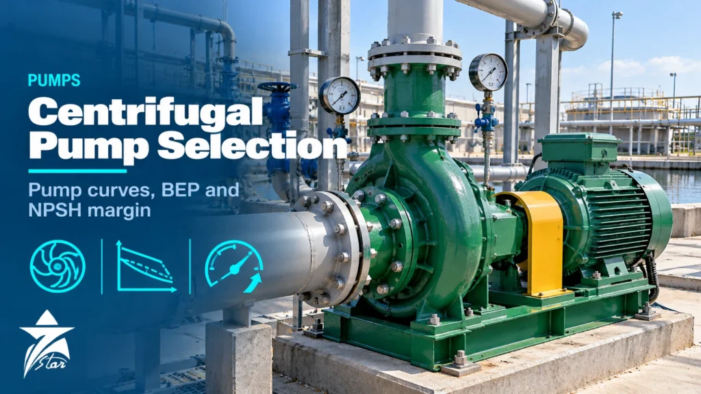
A pump that was selected on the duty point alone will often run, but it rarely runs well. Seals fail early, bearings overheat, impellers pit and the motor draws more power than the datasheet promised. Good centrifugal pump selection is about where the pump will actually operate across its whole life, not just at one flow and one head on the process data sheet. This guide walks through reading a pump curve, staying close to the best efficiency point (BEP), building a system curve, calculating NPSH available against NPSH required, recognising cavitation and recirculation, and the data you need to send before asking for a quotation.
Centrifugal Pump Selection Starts With the System, Not the Pump
A centrifugal pump has no fixed flow. It operates wherever its head–flow curve crosses the system curve, so the system has to be defined first. The system curve has two parts: static head, which does not change with flow (elevation difference plus the difference in surface pressures between the destination and source vessels), and dynamic head, which rises roughly with the square of flow (friction in pipe, fittings, strainers, heat exchangers and the control valve).
Write down at least three system cases: normal, rated (normal plus the design margin the process engineer specifies) and minimum. If the destination pressure varies, for example a deaerator that operates between two pressures or a tank level that swings several metres, draw a system curve for each extreme. A pump that sits comfortably at BEP for the normal case can be pushed to runout when the receiving vessel is at its lowest pressure, or forced back toward shutoff when the control valve throttles.
- Static head: elevation of the discharge liquid surface minus suction liquid surface, plus the pressure difference converted to head of the pumped liquid.
- Friction head: calculated for the actual pipe length, roughness and fittings at rated flow, then scaled with flow squared for the curve.
- Control valve allowance: the pressure drop the valve needs to control, which disappears when the valve opens fully.
Reading a Centrifugal Pump Curve
A manufacturer’s performance curve normally shows several sets of data on a common flow axis: total differential head for a range of impeller diameters, efficiency contours or an efficiency line, power absorbed (often for water at specific gravity 1.0), and NPSH required. Each curve is for one speed, so a pump running on a variable frequency drive needs the curve at each relevant speed or the affinity laws applied to the rated curve.
Look for three points on the head curve. Shutoff head is the head at zero flow, which sets the maximum pressure the discharge piping and casing must withstand when the discharge valve is closed. The BEP is the flow where hydraulic efficiency peaks. Runout is the far right end of the published curve, where head falls away and NPSH required climbs steeply. A curve that is too flat makes flow control by throttling difficult and makes parallel operation unstable; specifications for pumps intended to run in parallel typically ask for head to rise continuously toward shutoff, often by at least 10% from the rated point.
Power is the other trap. Absorbed power on many curves keeps rising toward runout, so the motor must be sized for the highest flow the system can impose, not only the rated point. Correct the water-based power figure for the real specific gravity and, for viscous liquids, for viscosity, because higher viscosity reduces head and efficiency and raises power.
Why the Best Efficiency Point Matters
At BEP, liquid enters the impeller vanes at close to the design angle and leaves the volute or diffuser with balanced pressure around the impeller. Move away from BEP and the radial hydraulic load on the impeller rises, shaft deflection at the seal faces increases, vibration grows and internal recirculation starts. That is why seal and bearing life correlate with how far the pump runs from BEP much more than with the pump’s nominal efficiency.
The Hydraulic Institute standard ANSI/HI 9.6.3 defines a preferred operating region (POR) around BEP and a wider allowable operating region (AOR) set by the manufacturer. For many end-suction and between-bearing process pumps the POR is commonly quoted as roughly 70% to 120% of BEP flow. Practical selection targets are:
- Rated point between about 80% and 110% of BEP flow.
- Normal operating point as close to BEP as the system allows, ideally slightly to the left of BEP so that the pump moves toward BEP as internal clearances wear.
- Minimum continuous flow, stated by the manufacturer for both thermal and stable operation, above the lowest flow the process can demand; otherwise provide a minimum-flow bypass.
NPSH Available vs NPSH Required
Net positive suction head is the margin of absolute pressure above the liquid’s vapour pressure at the pump suction, expressed as head of liquid. Two values must be compared. NPSH available (NPSHa) belongs to the system and is calculated by the plant engineer. NPSH required (NPSHr) belongs to the pump and is measured by the manufacturer on a test stand.
NPSHa = absolute pressure on the suction liquid surface (as head) + static height of liquid above the pump centreline (negative if below) − suction line friction losses − vapour pressure of the liquid at pumping temperature (as head). Every term must use the same liquid density and absolute pressure. For a liquid at its boiling point in a vessel, such as a deaerator, condensate receiver or column bottom, the surface pressure equals the vapour pressure and NPSHa is simply the static height minus friction.
NPSHr published on the curve is normally NPSH3: the NPSH at which the pump’s total head drops by 3% because of vapour forming in the impeller eye. Cavitation has therefore already started at NPSH3. Bubbles begin to form well before the 3% head drop, which is why the pump must have margin above NPSH3, not just equality.
How Much NPSH Margin?
ANSI/HI 9.6.1 gives recommended NPSH margin ratios (NPSHa divided by NPSH3) that vary with the application, the pump’s suction energy and whether it runs inside the POR or out in the AOR, where more margin is needed. Low-energy pumps on cool water need less; high suction energy pumps, boiler feed pumps and hydrocarbons close to their bubble point justify more. API 610 additionally requires a minimum margin between NPSHa and NPSH3 across the flow range. A practical first screen many engineers use is NPSHa at least 1 m above NPSH3 with a ratio comfortably above 1.1 at rated flow, followed by a check with the manufacturer against the applicable standard.
| Item | NPSH available (system) | NPSH required (pump) |
|---|---|---|
| Who determines it | Process/plant engineer | Pump manufacturer, by test |
| What changes it | Vessel pressure, liquid level, liquid temperature, suction pipe size and length, strainer condition | Impeller eye design, speed, flow rate |
| Effect of higher flow | Falls, because suction friction rises | Rises, often steeply toward runout |
| Effect of higher temperature | Falls, because vapour pressure rises | Little direct change |
| Typical ways to improve | Raise vessel or lower pump, larger and shorter suction line, cool the liquid, keep strainer clean | Lower speed, larger impeller eye, inducer, double-suction impeller, booster pump |
Cavitation and Suction Recirculation
Classic cavitation happens when local pressure in the impeller eye drops below vapour pressure. Vapour bubbles form, are carried to higher-pressure zones on the vanes and collapse violently. The symptoms are a gravel-like noise, fluctuating discharge pressure, falling head and pitting on the low-pressure (visible) side of the vane inlet. Damage is usually worst on water and hot water; many hydrocarbon mixtures cavitate less aggressively because they vaporise over a temperature range.
Suction recirculation looks similar but has a different cause. At low flow, liquid at the impeller eye reverses direction and forms vortices that can cavitate even with ample NPSHa. Pitting then appears on the pressure (hidden) side of the vanes, and noise is often intermittent. Impellers designed for very low NPSHr, with high suction specific speed, are more prone to recirculation at reduced flow. The cure is operational: keep the pump nearer BEP, add a minimum-flow bypass or select an impeller with a more conservative eye.
- Pitting on the visible inlet side of the vanes: insufficient NPSHa; check temperature, level, strainer and suction losses.
- Pitting on the hidden pressure side of the vanes: operation at low flow causing suction recirculation.
- Damage at the vane outlet or volute cutwater: discharge recirculation from low flow, or an impeller-to-cutwater gap that is too small.
- Seal face damage with dry-running marks: vapour in the seal chamber, often linked to cavitation or poor venting.
Affinity Laws, Impeller Trimming and Variable Speed
For a given pump, flow is proportional to speed, head to the square of speed and power to the cube of speed. Impeller trimming follows similar relations for small trims, but accuracy falls for large reductions in diameter, and efficiency drops. Trimming is a one-time adjustment; a variable speed drive gives continuous adjustment and is attractive where the system is friction-dominated, because the operating point then slides along a curve close to BEP as speed changes.
Where static head dominates, slowing the pump moves the operating point quickly toward shutoff and into low-flow operation, so speed turndown must be checked against minimum continuous flow. NPSHr also falls with speed, which helps on suction-limited duties. If you plan to use a drive, see the points on derating, harmonics and motor insulation in our guide to variable frequency drive selection for hot climates.
Data to Collect Before Requesting a Quotation
A clear data sheet saves several rounds of clarification and makes it possible to compare offers on an equal basis. Collect:
- Liquid name and composition, pumping temperature (normal, minimum, maximum), specific gravity, viscosity and vapour pressure at pumping temperature.
- Solids content, particle size and any abrasive or crystallising tendency; chlorides, H2S or other corrosive components.
- Rated, normal and minimum flow; differential head or suction and discharge pressures for each case.
- NPSHa calculation at rated flow with the basis stated (minimum liquid level, maximum temperature).
- Applicable standard: API 610, ISO 5199, ISO 2858, ASME B73.1 or manufacturer’s standard; seal standard and flush plan.
- Driver type, power supply (voltage, frequency), hazardous area classification and temperature class, and whether a drive is used.
- Site conditions: maximum and minimum ambient, outdoor or indoor, dust, humidity and salt spray.
- Existing pump nameplate and curve if this is a replacement, plus any history of failures.
Accurate flow and pressure readings from the existing installation are valuable when replacing a pump that never performed well. A calibrated pressure transmitter or gauge on suction and discharge, plus a reliable flow reading (see how to choose the right flow meter), lets you plot the real operating point on the old curve before specifying the new one.
Installation Practice That Protects NPSH
- Keep the suction line short and at least one size larger than the pump suction nozzle where NPSH is tight; use an eccentric reducer flat side up to avoid trapped vapour.
- Provide a straight run of several pipe diameters before the suction flange; an elbow directly at the inlet, in the plane of the shaft, feeds a double-suction impeller unevenly.
- Size temporary start-up strainers for low pressure drop and fit a differential pressure gauge so operators know when to clean them.
- Check submergence at the sump or tank outlet to prevent vortices drawing air into the pump.
GCC Operating Conditions
Ambient temperatures near 50 °C affect pump selection in several ways. Liquid temperatures in above-ground tanks and exposed suction lines rise, raising vapour pressure and cutting NPSHa, particularly for light hydrocarbons, condensate and solvents. Motor cooling is reduced, so a motor rated for 40 °C ambient must be derated or specified for the higher ambient. Seawater pumps for desalination and cooling need materials such as duplex or super duplex stainless steel, nickel aluminium bronze or suitable coatings, because chlorides and warm water accelerate pitting and crevice corrosion. Wetted parts in sour service (H2S) should be selected to NACE MR0175 / ISO 15156, and outdoor installations in sand-laden air benefit from bearing isolators instead of simple lip seals.
Centrifugal Pump Selection Checklist
- System curves drawn for normal, rated and minimum cases, including vessel pressure extremes.
- Rated point within roughly 80–110% of BEP; normal point close to BEP.
- Minimum continuous flow confirmed and protected by a bypass if needed.
- NPSHa calculated at maximum temperature and minimum level; margin over NPSH3 checked against ANSI/HI 9.6.1 or API 610.
- Head rising to shutoff; shutoff pressure within casing and piping rating.
- Motor sized for end-of-curve power, actual specific gravity and site ambient.
- Materials checked for chlorides, H2S, solids and temperature.
- Seal arrangement and flush plan defined.
- Impeller diameter leaves room to increase or trim.
Sourcing Centrifugal Pumps Through Seven Star LLC
Seven Star LLC supplies centrifugal pumps, spare impellers, seals and wear parts, and electric motors on request for plants in Oman and the GCC. We can help with selection and with cross-checking part numbers against your existing nameplate and curve; availability and lead time are confirmed at quotation.
Send us your pump data sheet, a nameplate photo of the existing unit or your RFQ, and we will come back with matching options for review.
Frequently asked questions
What is the difference between NPSHa and NPSHr?
NPSHa is the absolute suction head above vapour pressure that the system provides at the pump inlet, calculated by the plant engineer. NPSHr is what the pump needs, measured by the manufacturer and usually published as NPSH3, the point where head falls by 3%. NPSHa must exceed NPSH3 by a margin, because cavitation has already begun at NPSH3.
How far from BEP can a centrifugal pump run?
The Hydraulic Institute defines a preferred operating region around BEP, commonly about 70% to 120% of BEP flow for many pump types, and a wider allowable region set by the manufacturer. For long seal and bearing life, place the rated point at roughly 80% to 110% of BEP and keep normal operation close to it.
Why does my pump cavitate even though NPSHa is higher than NPSHr?
Either the margin is too small for that pump's suction energy, or the pump is running at low flow and suffering suction recirculation. Recirculation damage typically appears on the pressure side of the vanes, while NPSH-related cavitation pits the visible inlet side. Check actual flow, liquid temperature and strainer condition.
How do I calculate NPSH available?
Add the absolute pressure on the liquid surface (as head) to the liquid height above the pump centreline, then subtract suction line friction losses and the liquid's vapour pressure at pumping temperature, all in head of the pumped liquid. Use the minimum liquid level and maximum temperature for the design case.
Is it better to trim the impeller or use a VFD?
Trimming permanently matches the pump to a fixed, over-estimated duty and is simple, but efficiency falls with large trims. A variable speed drive suits friction-dominated systems with changing demand. In static-head-dominated systems, check that reduced speed does not push the pump below its minimum continuous flow.
What information should I send for a pump quotation?
Liquid properties at pumping temperature, rated, normal and minimum flow with matching heads, NPSHa, the applicable standard, seal requirements, driver and power supply details, hazardous area classification and site conditions. For replacements, include the existing nameplate, curve and failure history.
Was this guide helpful?One click helps us write better guides for engineers.
Thank you! Glad it helped. Need this equipment for your project? Request a quotation
Thank you. We will use this to improve the guide.