Insulation monitoring for unearthed AC/DC control circuits
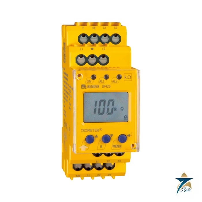
The Bender IR425-D4-2 is an ISOMETER insulation monitoring device for unearthed AC/DC control circuits (IT systems) from 0 to 300 V. It watches the insulation resistance between the system and earth and switches one of two separate alarm relays when the value falls below a pre-warning or an alarm threshold. The datasheet lists typical uses: AC/DC control and auxiliary circuits of machines to IEC 60204-1, auxiliary circuits to DIN VDE 0100-725, power plants, elevators, automation systems and smaller AC/DC IT systems such as lighting circuits.
The -2 in the type code means the 70 to 300 V AC/DC supply version; the -1 version takes 16 to 72 V AC or 9.6 to 94 V DC. The standard version has push-wire terminals (article number B71036402); the same type is available with screw terminals as B91036402, and the W versions (IR425-D4W) add increased shock and vibration protection.
Technical specification
| Parameter |
Specification |
| Type / article numbers |
IR425-D4-2: B71036402 (push-wire) and B91036402 (screw terminals); IR425-D4W-2: B71036402W and B91036402W |
| Standard |
Insulation monitoring device per IEC 61557-8; AMP measuring principle |
| Nominal system voltage Un |
AC/DC 0 to 300 V, 15 to 460 Hz |
| Supply voltage Us (-2 version) |
AC/DC 70 to 300 V, 15 to 460 Hz; power consumption max. 4 VA |
| Response values |
Ran1 and Ran2 adjustable 1 to 200 kOhm; preset 20 kOhm / 10 kOhm (Un up to 72 V) or 46 kOhm / 23 kOhm (Un above 72 V) |
| Operating error / hysteresis |
Plus/minus 0.5 kOhm (1 to 5 kOhm) and plus/minus 15 % (5 to 200 kOhm); hysteresis +1 kOhm / +25 % |
| Response time |
max. 2 s at RF = 0.5 x Ran and Ce = 1 uF; starting delay 0 to 10 s; response delay 0 to 99 s |
| Measuring circuit |
Measuring voltage max. 12 V; measuring current max. 200 uA at RF = 0; internal DC resistance min. 62 kOhm; internal impedance min. 60 kOhm at 50 Hz; extraneous DC voltage max. 300 V |
| System leakage capacitance Ce |
max. 20 uF |
| Display |
Multi-functional LC display, 1 kOhm to 1 MOhm, plus/minus 15 % (plus/minus 0.5 kOhm between 1 and 5 kOhm); password off or 0 to 999 |
| Alarm outputs |
2 changeover contacts (K1, K2), N/O or N/C operation selectable; 10 000 switching cycles; AC-13 230 V 5 A, AC-14 230 V 3 A, DC-12 24 V 1 A, 110 V 0.2 A, 220 V 0.1 A |
| Insulation coordination |
Rated insulation voltage 250 V; rated impulse voltage 4 kV; pollution degree 3; voltage test 2.2 kV |
| Connection |
Screw terminals (rigid 0.2 to 4 mm2, 0.5 to 0.6 Nm) or push-wire terminals (rigid 0.2 to 2.5 mm2, stripping length 10 mm) |
| Environment |
Operating temperature -25 C to +55 C; climatic class 3K22; mechanical class 3M11 (3M12 for W version); EMC per IEC 61326-2-4 |
| Enclosure |
Polycarbonate, UL 94 V-0; IP30 internal parts, IP20 terminals; 36 mm wide two-module housing; DIN rail IEC 60715 or 2 x M4 screws with mounting clip; any mounting position |
| Weight |
approx. 150 g |
How the IR425 works in a control circuit
The measured insulation resistance is shown on the LC display, so a change when a new circuit is connected is visible immediately. When the value falls below a response value, the response delay starts, then the matching relay and alarm LED switch. Two separately adjustable alarms distinguish a pre-warning from a real alarm. The display also shows a plus or minus sign to distinguish faults on the positive or negative conductor in DC. The device checks its own connections to the system (L1, L2) and to earth (E, KE) every 24 hours or when the test button is pressed or supply voltage is applied; a broken lead gives the error codes E.02 (system) or E.01 (PE) and switches relay K2. After first connection the preset function measures the nominal system voltage and sets basic response values automatically.
Selection and wiring notes
- Choose the supply version by the auxiliary supply available: -1 for 16 to 72 V AC or 9.6 to 94 V DC, -2 for 70 to 300 V.
- Connect E and KE separately to PE; protect the system connection L1, L2 with a fuse (6 A recommended).
- If the device is powered from the IT system itself, both supply lines must be fused.
- The test/reset button can be external with cable length up to 10 m; a mounting frame XM420 (B990994) and screw-mounting clip (B98060008) are listed accessories.
- Fault memory, relay operating mode and response delay are parameterised on the front plate and can be password protected.
Where Bender ISOMETERs are used in the GCC
Unearthed control circuits keep a machine running through a single earth fault, but only if the first fault is found before a second one appears. That is why insulation monitoring is common in power station auxiliaries, process plants, lifts and crane controls. The IR425-D4-2 suits 24 to 230 V control circuits up to 300 V. For higher IT-system voltages see the iso685-D-P ISOMETER on this site. Browse the relays category for related monitoring devices.
Selection and installation notes
Insulation and residual current monitoring devices are selected from the system type (IT, TN or TT), the system voltage, the leakage capacitance and the alarm levels needed. Connect the device to the system and to earth as the manual shows, set the response values from the system design, check the coupling or measuring current transformer and its wiring, and test the alarm and relay outputs after commissioning. Do not do an insulation test of the plant with the monitor connected unless the manual allows it.
Information needed for a quotation
Send the full model code, the quantity, the delivery location in Oman or the GCC, the intended use and any accessories needed, so that the complete package can be quoted together.
Documents and supply information
The manufacturer data sheet is attached to this page and should be read together with the project specification and the site risk assessment before a purchase is confirmed. Ratings, standards and dimensions are quoted as printed on that sheet. Lead time, stock position and certificates available with the shipment are confirmed in the quotation, and we supply to Oman and the wider GCC region for industrial, utility and building services projects.
Frequently asked questions
What does the IR425-D4-2 monitor?
The insulation resistance of unearthed AC/DC control circuits with a nominal voltage of 0 to 300 V (IT systems), with two adjustable alarm thresholds from 1 to 200 kOhm.
What is the difference between IR425-D4-1 and IR425-D4-2?
Only the supply voltage: the -1 version takes 16 to 72 V AC or 9.6 to 94 V DC, the -2 version takes 70 to 300 V AC or DC.
Which article number is the push-wire version?
B71036402 for push-wire terminals and B91036402 for screw terminals.
Does it check its own connections?
Yes, the connections to the system and to earth are checked every 24 hours, on test, and when supply voltage is connected.
Does Seven Star LLC manufacture Bender products?
No. Seven Star LLC is an independent supplier in Muscat. Confirm the supply voltage and terminal type with us before ordering.











Reviews
There are no reviews yet.