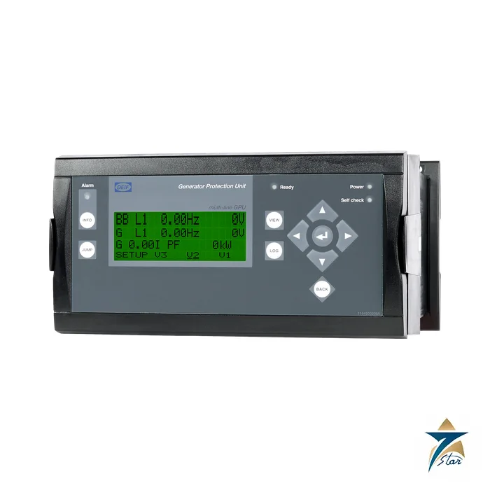
A marine generator protection unit
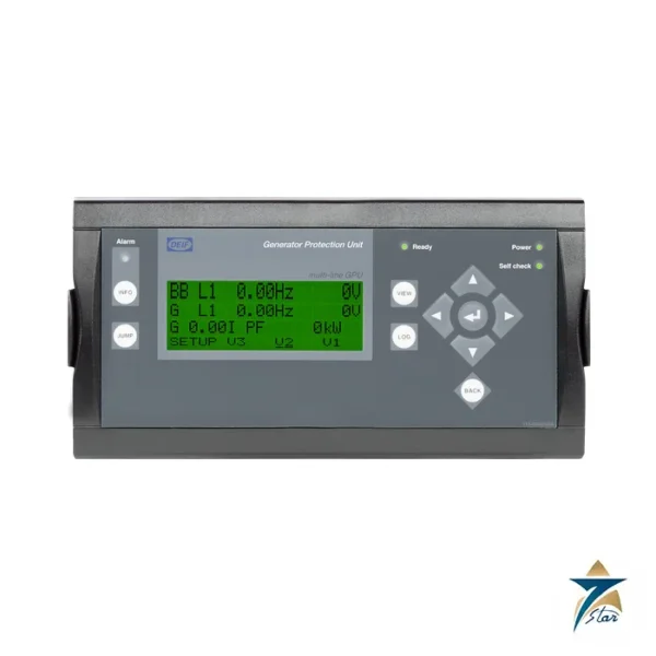
The DEIF GPU-3 is a compact microprocessor-based Generator Protection Unit for a synchronous or asynchronous generator, supplied in this data sheet as the GPU-3 Marine. It contains the galvanically separated 3-phase measuring circuits and is intended for land and marine applications; DEIF states it is marine-approved by all major classification societies and UL/cUL Listed. It suits PLC-controlled systems, with interfacing through digital and analogue I/O or serial communication.
Technical specifications
| Parameter |
Specification |
| Manufacturer / series |
DEIF A/S, Multi-line 2, GPU-3 (SW 3.06.x or later) |
| Variants |
01 with display 2912110030-01; 02 without display 2912110030-02; 03 with display plus F1 2912110030-03 |
| Measuring voltage |
100 to 690 V AC +/-20 percent; UL/cUL Listed 600 V AC; max 0.25 VA per phase |
| Measuring current |
1 A or 5 A AC; max 0.3 VA per phase; 4 x In continuous, 20 x In for 10 s, 80 x In for 1 s |
| Frequency |
30 to 70 Hz |
| Auxiliary supply |
12/24 V DC nominal (8 to 36 V DC), terminals 1-2 max 11 W and 98-99 max 5 W; 2 A slow-blow fuse |
| Accuracy |
Class 1.0 to IEC/EN 60688 |
| Relay outputs |
250 V AC / 30 V DC, 5 A (UL/cUL 250 V AC / 24 V DC, 2 A resistive) |
| Analogue outputs |
0(4) to 20 mA and +/-25 mA, galvanically separated, load max 500 ohm |
| Mounting |
DIN rail or base mount with six screws |
| Protection degree |
Unit IP20; display IP40, IP54 with gasket (option L); IP54 display required for RS-approved applications |
| Operating temperature |
-25 to 70 °C (-25 to 60 °C with option N); altitude to 4000 m |
| Weight |
Base unit 1.6 kg; display 0.4 kg |
| Approvals |
Marine-approved by major classification societies; UL/cUL Listed to UL508; UL/cUL Recognized to UL2200 |
| Document |
Data sheet 4921240352K (EN), 17 pages |
Standard protections
The standard protection set includes generator reverse power (2 steps), over-current (6 steps), voltage-dependent and inverse-time over-current, over and under voltage and frequency, overload (5 steps), current and voltage unbalance, over-excitation and loss of excitation, plus busbar over and under voltage and frequency and busbar voltage unbalance. Response times with delay at minimum are under 50 ms for busbar voltage and frequency, under 200 ms for reverse power and over-current, and under 40 ms for fast over-current.
Options and ordering
Options include A mains protection, C add-on generator protection, D1 voltage control and G2 synchronisation, E and F analogue transducer outputs, H serial communication (Modbus, Profibus, MTU, CAN J1939 engine interfaces), M4 engine control and protection, N Ethernet and Y display layouts such as engine and breaker control. Not all options fit one unit; the hardware overview in the sheet shows slot allocation. The sheet’s worked example is item 2912110030-03 GPU-3 Marine 03 with M4, Y1 and H2. For gas engines see the GPU-3 Gas page.
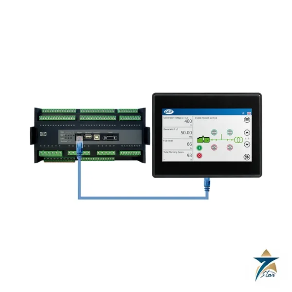
Accessories listed for the GPU-3 are the standard display unit DU-2 (2912210050), an additional DU-2 on CAN bus (2912890030, two per unit), the AOP-1 operator panel (2912890040) and AOP-2 panel (2912890050, up to five per unit), the IP54 display gasket (1134510010) and display cables of 1 m (1022040064), 3 m (1022040076) and 6 m (1022040057). A USB cable (1022040065) connects the PC utility, and a crossed Ethernet cable (1022040055) serves option N. On start-up the unit runs a cyclical self-test and reports faults in clear text and on a status relay. The separate display can be fitted on the unit or on the switchboard door, and up to two further displays can be installed within 200 m.
How the DEIF GPU-3 works
The unit reads the three-phase voltage and current of the generator through galvanically separated circuits. It compares them with the set limits. When a value goes out of range for longer than its delay, the unit trips a relay, which opens the breaker or stops the set.
Where the GPU-3 is used
- Ship generators
- Land generator sets
- PLC-controlled power systems
- Synchronous generators
- Asynchronous generators
Selection checklist for the GPU-3
- Variant 01, 02 or 03
- Display needed or not
- Measuring voltage
- Current input of 1 A or 5 A
- Supply of 12 or 24 V DC
- Relay and analogue outputs
- Display enclosure class
- Operating temperature
Installation, commissioning and maintenance notes for the GPU-3
Fix the unit on a DIN rail or on a base with six screws. Wire the voltage and current inputs with correct polarity. Connect the supply with a 2 A slow-blow fuse. Set the protection limits and the delays, then test the relays. Check the settings after any change to the plant.
Requesting a quotation for the DEIF GPU-3
Please send the variant, the generator data and the display option. Seven Star LLC serves industrial customers in Oman and the GCC and replies with a quotation based on the information provided.
GPU-3 variants
Variant 01 has a display, variant 02 has no display and variant 03 has a display plus option F1.
GPU-3 measuring voltage
The measuring voltage is 100 to 690 V AC and the frequency is 30 to 70 Hz.
GPU-3 measuring current
The current input is 1 A or 5 A AC.
GPU-3 auxiliary supply
The supply is 12/24 V DC, within 8 to 36 V DC.
GPU-3 accuracy
The accuracy is Class 1.0 to IEC/EN 60688.
GPU-3 relay outputs
The relays switch 250 V AC at 5 A.
GPU-3 analogue outputs
The analogue outputs are 0(4) to 20 mA and plus or minus 25 mA.
GPU-3 reverse power protection
The reverse power protection has two steps.
GPU-3 over-current protection
The over-current protection has six steps.
GPU-3 mounting and weight
The base unit weighs 1.6 kg and the display weighs 0.4 kg.
Protection records for the GPU-3
Record the software version, the limits and the delay of each protection step.
Choosing the right GPU-3 variant
Choose the version with a display when settings are changed on site.
Documents and quotation
This page carries the DEIF GPU-3 data sheet 4921240352K (EN). To quote, we need the variant, option set, quantity and the application it is destined for. See Diesel Generator Spare Parts for related DEIF controllers and generator control products.





Reviews
There are no reviews yet.