Locking assembly for large peripheral forces without axial shift
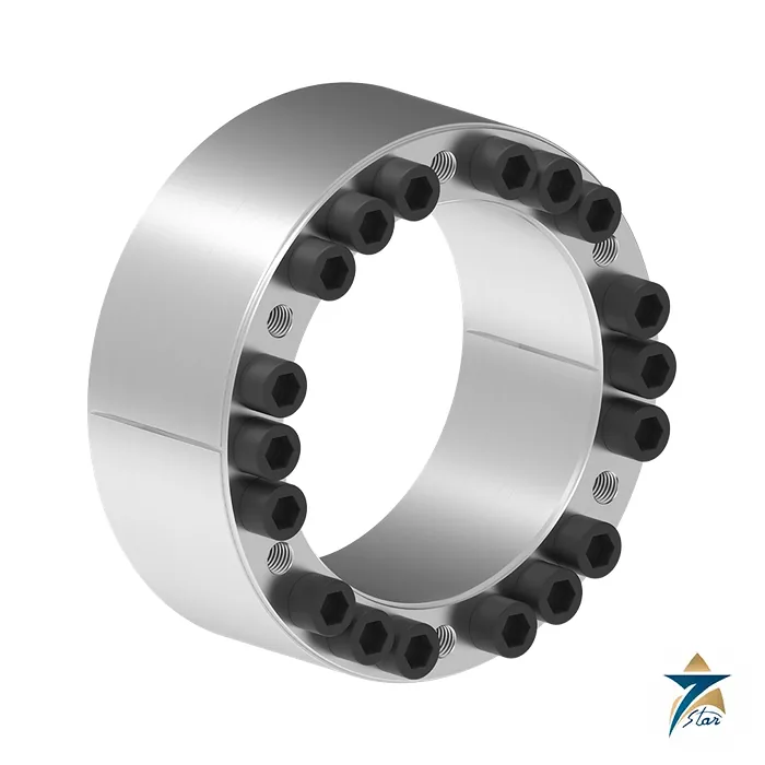
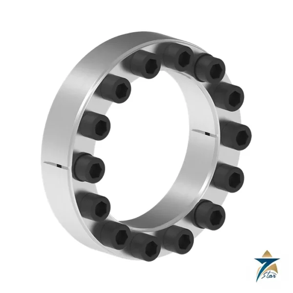
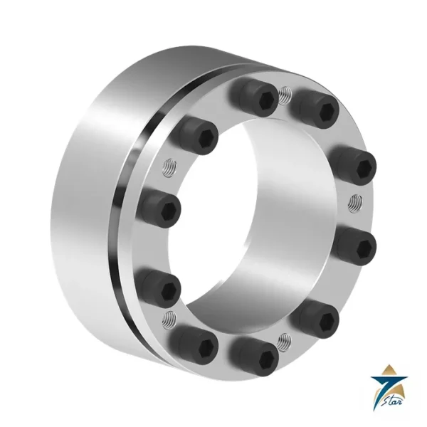
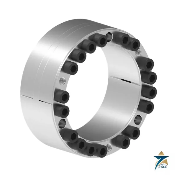
The RfN 7014 uses long, flat cones to move the highest torques and axial forces that a single self-centring locking assembly can carry. Its multi-part construction means that the assembly, the shaft and the hub stay put relative to one another while the screws are tightened, so there is no axial shift of the hub during mounting. Shaft and hub are loaded in compression only, which RINGFEDER presents as extra safety compared with three-piece designs. Sizes run from 60 to 300 mm shaft diameter.
The wide construction gives large guide lengths, so the assembly centres itself, and the series is aimed at heavy drives where torque of 4,130 Nm and upward has to pass through a keyless joint: large gear wheels, couplings and sheaves on slow, high-torque shafts.
Technical specifications
| Parameter |
Specification |
| Manufacturer |
RINGFEDER POWER TRANSMISSION GmbH, Groß-Umstadt, Germany |
| Series |
RINGFEDER RfN 7014 locking assembly, self-centring, multi-part with long flat cones |
| Shaft diameter d |
60 to 300 mm |
| Hub bore diameter D |
100 to 390 mm |
| Overall length L |
60 to 156 mm |
| Transmissible torque T |
4,130 Nm (60 x 100) to 245,000 Nm (300 x 390) |
| Transmissible axial force Fax |
138 kN to 1,633 kN |
| Maximum transmissible torque Tmax |
5,120 Nm to 310,335 Nm |
| Surface pressure on shaft pW / hub pN |
179 to 263 N/mm2 / 117 to 179 N/mm2 |
| Locking screws |
M10 x 45 to M20 x 120; 8 to 26 screws depending on size |
| Screw tightening torque TA |
84 Nm to 690 Nm |
| Weight |
1.8 kg to 49 kg |
| Surface finish |
Shaft and hub bore Ra 3.2 um or better |
| Tolerances |
Shaft k9 to h9, hub N9 to H9 |
| Ordering example |
RfN 7014 150 210 (d = 150 mm, D = 210 mm) |
Selected sizes from the tech paper
The table holds 20 sizes between 60 and 300 mm:
| d x D (mm) |
L (mm) |
T (Nm) |
Fax (kN) |
Screws |
TA (Nm) |
Weight (kg) |
| 60 x 100 |
60 |
4,130 |
138 |
8 x M10 x 45 |
84 |
1.8 |
| 80 x 130 |
74 |
11,650 |
291 |
12 x M12 x 55 |
145 |
3.7 |
| 100 x 160 |
94 |
19,700 |
394 |
12 x M14 x 70 |
230 |
7.2 |
| 150 x 210 |
94 |
42,900 |
572 |
18 x M14 x 70 |
230 |
10 |
| 200 x 270 |
110 |
105,000 |
1,050 |
23 x M16 x 80 |
355 |
18.8 |
| 240 x 320 |
134 |
153,000 |
1,275 |
24 x M18 x 100 |
485 |
29.8 |
| 300 x 390 |
156 |
245,000 |
1,633 |
24 x M20 x 120 |
690 |
49 |
Removal step, series use and hub sizing
One design note is specific to this series: for removal, the tech paper requires a step in the hub or the shaft, as drawn in its installation sketch, so plan the shoulder at design stage. At most two RfN 7014 assemblies can be installed in series; the transmission values of the table are then doubled. The values apply to assemblies installed in oiled condition, and RINGFEDER says a lower screw tightening torque is possible but should be agreed with its specialists.
Minimum hub outside diameter DN is tabulated for hub yield strengths of 200, 300 and 400 N/mm2. For the 150 x 210 size that is 510, 340 and 301 mm; the table prints dashes instead of a value for some sizes at 200 N/mm2. The maximum transmissible torque Tmax for 150 x 210 is 52,489 Nm against 42,900 Nm rated.
Confirm before ordering: hub yield strength, whether a shoulder for removal can be provided, and the torque including shock loads.
The calculation chapter of the product paper supplies the equations behind the DN values: factor C3 is 0.6 for one assembly in a hub at least twice the ring width long, 0.8 for two or more assemblies, and 1.0 where the hub length equals the ring width. Because the real friction coefficient and the hub shape scatter, the paper treats the results as approximations.
Key features of the RfN 7014 design
- Self-centring construction: the long, flat cones and wide body provide generous guide lengths, so the hub is centred on the shaft by the assembly itself without an additional pilot fit in most layouts.
- No axial hub movement during tightening: because the multi-part design keeps shaft, hub and assembly fixed relative to each other, gears, sheaves and coupling halves stay at their set axial position, which is important where tooth contact or belt alignment has been set precisely.
- Keyless, backlash-free joint: torque and axial force are transmitted by friction, so there is no keyway to weaken the shaft and no play to hammer out under reversing or shock loads.
- Combined loads: the tabulated torque T and axial force Fax describe the capacity of the joint; where both act together the resulting load has to be checked against the catalogue values.
- Series installation: up to two assemblies can be fitted one behind the other to double the transmission values, a practical option where hub length is available but a larger diameter is not.
How to select the right size
Selection starts from the shaft diameter d, which fixes the candidate size, and the hub bore D that follows from it. Then compare the required torque, including service factors for start-up, shock and reversing duty, with the rated torque T of that size. If an axial force also acts, for example from helical gearing, include it in the check. Next, verify the hub: the minimum hub outside diameter DN depends on the yield strength of the hub material, and a hub that is too thin can yield under the radial pressure the assembly generates. Finally, confirm that the shaft and hub tolerances (shaft k9 to h9, hub N9 to H9) and the surface finish of Ra 3.2 µm or better can be held in machining.
Points to check on the drawing
- Shoulder or step for removal, as required by the tech paper.
- Clearance for a torque wrench on the locking screws, since sizes use from 8 to 26 screws.
- Hub length relative to ring width, which influences the C3 factor in the hub calculation.
Installation and maintenance guidance
Clean the shaft and hub bore and remove burrs and paint. The published values apply to assemblies installed in oiled condition, so lubricate contact surfaces and screws as the manufacturer instructs and do not use lubricants containing molybdenum disulphide or other additives unless the instructions allow it. Tighten the locking screws in several passes in a crosswise sequence with a calibrated torque wrench until the specified tightening torque TA (84 Nm up to 690 Nm depending on size) is reached on every screw. After a short running-in period, a check of the screw torque is good practice on heavy drives. For removal, use the step provided in the hub or shaft and follow the release procedure in the installation instructions.
Use in Oman and GCC industrial plants
Keyless locking assemblies of this size class are common on slow, high-torque drives such as conveyor pulleys in cement and mining, large gear couplings at desalination and power plants, and mill or crusher drives. In coastal and humid sites around Sohar, Duqm and Salalah, corrosion on exposed shaft ends and screw heads is a real concern: protect exposed surfaces after installation and inspect them during planned shutdowns. In dusty inland locations, keep the contact surfaces clean during mounting, because grit trapped in the joint reduces the friction and the effective clamping. High ambient temperatures change the fit between steel parts only slightly, but heat from adjacent gearboxes should be considered when the hub is made of a different material from the shaft.
What to include in your RFQ
- Full designation, for example RfN 7014 150 210, or shaft diameter d and hub bore D.
- Nominal torque, peak or shock torque, and any axial force.
- Hub material and yield strength, hub outside diameter and length.
- Whether one or two assemblies are planned in series.
- Quantity, required delivery date and the equipment the assembly is for.
Documents and quotation
The attached PDF is the RINGFEDER tech paper for the RfN 7014 (05.2024). Large gear units for such shafts are listed under Electric Motors and Gear Units. Send shaft diameter, torque, hub material and speed for a size check.

Reviews
There are no reviews yet.