
- Vibration Monitoring
- Industrial Communications
- PLC & I/O Cards
- Automation Accessories
- Controllers & Data Acquisition
- AC Drives
- Industrial Computers
- Encoders
- Safety Switches & Guard Locking
- Isolator & Barrier
- Automation Software
- HMI Displays
- Motor Soft Starters
- Servo Drives
- CCTV & Security
- Robotics
- Pneumatic Cylinders
- Machine Vision
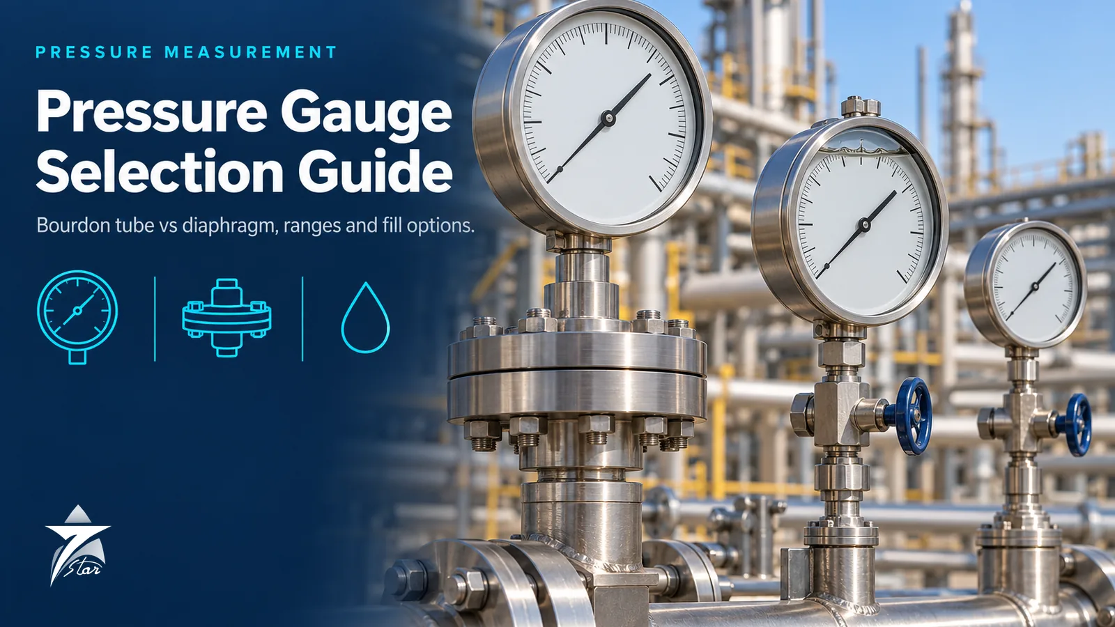
Pressure Gauge Selection Guide: Bourdon Tube vs Diaphragm, Accuracy Classes, Liquid Filling, Seals and Switches
Mechanical pressure gauges are the most numerous instruments in any process plant, and because each one is cheap, pressure gauge selection is often reduced to copying the last purchase order. The result is familiar to anyone who has walked a plant: pointers vibrating across half the dial on pump discharges, cloudy windows, gauges pegged at full scale after an overpressure event, and diaphragm-sealed gauges reading high every afternoon in the sun. Each of these traces back to a specification decision.
This guide covers element types, accuracy classes under EN 837 and ASME B40.100, range selection, liquid filling and dampening, safety patterns, materials, diaphragm seals, differential pressure gauges and pressure switches, with attention to the heat, UV and corrosion conditions found at Omani sites.
Standards and Element Types
EN 837-1 covers Bourdon tube gauges, EN 837-3 covers diaphragm and capsule gauges, and EN 837-2 gives selection and installation recommendations. In North American specifications the equivalent reference is ASME B40.100. The element type is the first decision because it determines range, overload capability and media compatibility.
| Element | Typical range | Strengths | Limitations | Typical use |
|---|---|---|---|---|
| Bourdon tube (C-shaped, helical or spiral) | From below 1 bar up to very high pressures; helical or spiral elements for the higher ranges | Simple, robust, wide range, low cost | Limited overload capacity; not suited to very low pressures; process medium enters the tube | General process, utilities, hydraulics |
| Diaphragm (flat plate) | Low to medium pressures, typically mbar to tens of bar | High overload capacity on many designs; open-flange versions handle viscous or crystallising media; easy to fit with a flushing connection | Larger and more expensive; lower maximum range | Corrosive, viscous or contaminated media, low pressures |
| Capsule | Very low pressures, typically mbar range | High sensitivity at low pressure | Gas service only; poor overload capacity | Gas pressure, draft, burner and ventilation pressures |
Accuracy Classes
EN 837 defines accuracy classes as the permissible error as a percentage of span: 0.1, 0.25, 0.6, 1.0, 1.6, 2.5 and 4.0. Most process gauges are class 1.0 (common on 100 mm and 160 mm dials) or class 1.6 (common on 63 mm dials). Classes 0.1 to 0.6 are test gauges for calibration and reference duties. ASME B40.100 uses grades instead, from 4A (0.1%) down to grades A and B, where the permitted error is tighter in the middle half of the scale than at the ends.
| EN 837 class | Permissible error (% of span) | Typical application |
|---|---|---|
| 0.1 / 0.25 | ±0.1 / ±0.25 | Reference and calibration test gauges |
| 0.6 | ±0.6 | Precision test gauges, critical local indication |
| 1.0 | ±1.0 | Standard process gauges, 100 mm and 160 mm dials |
| 1.6 | ±1.6 | Smaller process gauges, utilities |
| 2.5 / 4.0 | ±2.5 / ±4.0 | Low-cost indication, small dials, HVAC |
Two practical points follow. First, error is a percentage of span, so a class 1.0 gauge of 0–100 bar may be 1 bar wrong at any point, which is 4% of reading at 25 bar. Second, EN 837-1 allows an additional temperature error for Bourdon gauges, typically stated on datasheets as around ±0.4% of span per 10 K deviation from the 20 °C reference. A gauge at 60 °C in the Omani summer can therefore carry an extra 1.6% of span on top of its class.
Dial size is a readability choice as much as an accuracy one. 63 mm suits compact skids and manifolds, 100 mm is the common process size, and 160 mm is preferred where the gauge is read from a distance or across a walkway.
Range Selection and Overpressure
Common practice, reflected in EN 837-2, is to select the range so the normal operating pressure falls in the middle third of the scale, with steady pressure not exceeding about 75% of full scale and fluctuating pressure not exceeding about two thirds. This keeps the element within its elastic range and protects against fatigue. Where the gauge may see pump shut-off head, a pressure test or a relief valve set pressure, check the overload rating on the datasheet; Bourdon gauges often have limited overload capability, while many diaphragm designs tolerate several times full scale. Overpressure stops or gauge protectors are available where occasional surges cannot be avoided.
Liquid Filling, Dampening and Pulsation
Pump discharges, reciprocating compressors and vibrating skids destroy dry gauges quickly through pointer flutter and wear of the movement. Liquid filling damps both the pointer and the movement. Glycerine is common for general service, while silicone oil offers a wider temperature range and is preferred where temperature swings are large. Neither should be used on oxygen or strong oxidiser service, where halocarbon fills or dry gauges cleaned for oxygen service are required.
For severe pulsation, add a snubber or restrictor in the connection, or use an adjustable dampening device. A restrictor screw reduces the transmitted pulsation but can block with dirty media, so it suits clean fluids only.
Safety Pattern Gauges
A Bourdon tube that ruptures releases process fluid into the case. EN 837-1 defines safety levels for case design, and the highest, designated S3, combines a solid baffle wall between the measuring element and the dial with a blow-out back. If the element fails, the pressure is vented through the back, away from the operator standing in front of the window. S3 gauges are good practice for high pressures, toxic or flammable gases, and any gas service where the stored energy is significant. Stainless steel liquid-filled gauges such as the WIKA 233.50 are widely used for general process duty; confirm the available safety level, accuracy class and dial size for the specific variant on the datasheet.
Materials and Sour Service
Stainless steel 316 or 316L wetted parts are the default for process service. Monel is used for some seawater, hydrofluoric acid and chloride-rich duties, and other alloys or lined seals are selected for strongly corrosive chemicals. For sour service containing H2S, wetted materials should comply with NACE MR0175 / ISO 15156, which must be stated explicitly on the order because a standard 316 gauge is not automatically certified for it. Case and bezel material should also be stainless for coastal sites; painted steel cases corrode quickly near the sea.
Diaphragm Seals
A diaphragm seal isolates the gauge or transmitter from the process using a flexible diaphragm and a sealed fill fluid. It is needed for corrosive, viscous, crystallising, slurry, hygienic or hot media, and wherever the process must not enter the instrument. Seals can be mounted directly or through a capillary for high-temperature or remote reading. Flanged seals such as the WIKA 990.27 diaphragm seal are a common choice on process lines; check the diaphragm diameter, flange rating and fill fluid on the datasheet.
Seals introduce temperature effects that are often underestimated. Fill fluid expands with temperature and pushes the diaphragm, producing a zero shift. Smaller diaphragms, longer capillaries and lower pressure ranges make the error worse. A low-range gauge on a small seal with a long capillary in direct sun can show a significant error between morning and afternoon. Mitigations include larger diaphragms, shorter capillaries, direct mounting, sunshades and fill fluids chosen for the actual process and ambient temperature limits. For vacuum service, the fill fluid and filling method must be suitable.
Differential Pressure Gauges
DP gauges indicate filter and strainer loading, pump suction and discharge differences, and level in some vessels. The key specification points are the DP range, the maximum static pressure each side can tolerate, and one-sided overload protection so that a pressurised high side with an isolated low side does not damage the element. Units such as the WIKA DPGT43 differential pressure gauge are used on filter skids; confirm the static pressure rating and whether integral contacts or a transmitter output are available. A three-valve manifold makes zero checks and isolation straightforward.
Pressure Switches
Pressure switches provide discrete signals for alarm, interlock and equipment protection, such as low lube oil pressure or high discharge pressure. Specify the set point and whether it is rising or falling, the deadband (the difference between switching and resetting points, which may be fixed or adjustable), the contact type (typically SPDT), electrical rating, and whether gold-plated contacts are needed for low-energy signals into PLC or intrinsically safe circuits. Compact switches such as the WIKA PSM01 pressure switch suit machinery and utility duties. If the switch is part of a safety instrumented function, it must have suitable reliability data or certification for the required SIL, and many operators now prefer transmitters with trip amplifiers for safety duties because they allow diagnostics and continuous monitoring of the signal.
Gauge or Transmitter
A local gauge is right when the value is needed only by an operator at the equipment. A transmitter is needed when the value must reach the control system, be trended, alarmed or used in control. General-purpose units such as the WIKA A-10 pressure transmitter or the Danfoss MBS 3000 suit machinery, utilities and OEM skids, while process plants generally specify full process transmitters. For more detail on that choice, see our pressure transmitter selection guide. Many critical points have both: a transmitter for the control system and a gauge for local verification.
Installation Practice
Fit an isolation valve or a block-and-bleed gauge valve so the gauge can be removed and vented safely. On steam, use a siphon (pigtail or U-tube) to form a condensate seal that protects the element from live steam. Mount gauges where they can be read and away from direct vibration sources, using remote mounting with a flexible line if needed. For gas service, mount above the tapping so condensate drains back; for liquid service, mount below so gas does not collect.
Considerations for Oman and the GCC
- UV exposure: polycarbonate and acrylic windows can yellow and craze in strong sunlight; laminated safety glass resists UV better.
- Heat on fill fluids: glycerine-filled gauges in direct sun can build internal pressure and leak through the vent or seal. Use the vent plug correctly and consider silicone fill for wide temperature swings.
- Condensation: gauges cooled overnight in humid coastal air draw in moisture, which fogs dry gauges. Liquid-filled or sealed hermetic cases avoid this.
- Seal temperature errors: sunshades over diaphragm seals and capillaries reduce afternoon drift.
- Salt atmosphere: stainless cases, bezels and fittings are essential at Sohar, Sur, Duqm and Salalah.
Common Mistakes
- Choosing a range where normal pressure sits in the first quarter of the scale, which wastes accuracy.
- Fitting dry gauges on pump discharges and reciprocating compressors.
- Ordering standard 316 gauges for sour service without NACE MR0175 / ISO 15156 compliance stated.
- Using a capsule gauge on liquid service.
- Specifying a small diaphragm seal with a long capillary on a low range and accepting large temperature errors.
- Omitting a siphon on steam service.
Pressure Gauge Specification Checklist
- Process medium, temperature, normal and maximum pressure, pulsation and vibration known
- Element type selected (Bourdon, diaphragm or capsule)
- Range with normal pressure in the middle third and overload rating checked
- EN 837 accuracy class or ASME B40.100 grade defined
- Dial size, connection size and position (bottom or back) defined
- Liquid filling and fill type selected for the temperature range
- Safety level such as S3 specified for high-pressure or hazardous gas service
- Wetted material and NACE MR0175 / ISO 15156 compliance where needed
- Diaphragm seal type, fill fluid, capillary length and temperature error assessed
- Gauge valve, siphon, snubber or overpressure protector included
- Window material suitable for UV exposure
Sourcing Pressure Instruments Through Seven Star LLC
Seven Star LLC supplies and sources pressure gauges, diaphragm seals, DP gauges, pressure switches and transmitters for process plants and contractors in Oman and the GCC. Browse the pressure instrumentation category and the WIKA brand page. Include range, connection, dial size, accuracy class, fill and material requirements with each enquiry.
Send your pressure gauge or switch specification to Seven Star LLC through our contact page for a quotation.
Was this guide helpful?One click helps us write better guides for engineers.
Thank you! Glad it helped. Need this equipment for your project? Request a quotation
Thank you. We will use this to improve the guide.
Need a Quotation for Your Project?
Seven Star LLC supplies the industrial equipment covered in this article to customers across Oman and the GCC. Send us the part numbers, models or a short description with quantities, and our sales team will reply with a formal quotation.
- Genuine OEM products
- Supply across Oman & the GCC
- Formal quotation from our sales team
Free, no-obligation quotation · takes about 1 minute
Other enquiries: [email protected] · WhatsApp
More Blog



Frequently Asked Questions
EN 837-1 covers pressure gauges with Bourdon tube elements, including their accuracy classes, safety levels and testing. EN 837-3 covers diaphragm and capsule pressure gauges. EN 837-2 gives recommendations on selection and installation for both.
Under EN 837 the class is the permissible error as a percentage of the full span. A class 1.6 gauge with a range of 0 to 10 bar may therefore be up to 0.16 bar in error anywhere on the scale. Temperature effects can add further error when the gauge operates away from 20 °C.
Liquid filling damps the pointer and movement, which reduces wear and makes the gauge readable under vibration and pressure pulsation. It also prevents condensation inside the case. Silicone oil is used when a wider temperature range is needed, and neither fill is suitable for oxygen service.
Common practice is to place the normal operating pressure in the middle third of the scale. Steady pressure should not exceed about 75% of full scale and fluctuating pressure about two thirds. This gives good readability and avoids fatigue of the element.
A diaphragm seal is needed when the process medium is corrosive, viscous, crystallising, contains solids, is very hot, or must not enter the instrument. The seal transmits pressure through a fill fluid while isolating the gauge. Its temperature effect must be checked, especially on low ranges and long capillaries.
S3 is the highest safety level defined in EN 837-1 for gauge cases. It has a solid baffle wall between the measuring element and the dial and a blow-out back, so that if the element ruptures the pressure is released through the rear of the case. It is recommended for high pressures and hazardous gas service.