
- Vibration Monitoring
- Industrial Communications
- PLC & I/O Cards
- Automation Accessories
- Controllers & Data Acquisition
- AC Drives
- Industrial Computers
- Encoders
- Safety Switches & Guard Locking
- Isolator & Barrier
- Automation Software
- HMI Displays
- CCTV & Security
- Motor Soft Starters
- Servo Drives
- Robotics
- Pneumatic Cylinders
- Machine Vision
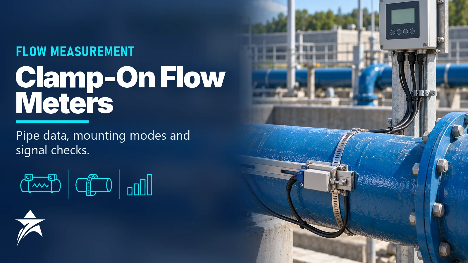
Clamp-On Flow Meter Installation: Pipe Data, Mounting Modes, Straight Runs and the Errors That Ruin Accuracy
A clamp-on ultrasonic meter promises flow measurement without cutting the pipe, stopping the process or buying a flanged spool, and in good conditions it delivers. But clamp-on flow meter installation is where most of the accuracy is won or lost. The transmitter calculates flow from pipe geometry and sound velocities that you type in, so a wrong outside diameter, an unknown cement lining or a location just after a pump can shift the reading by several percent while the display still looks perfectly stable. This guide focuses on the installation itself: the pipe data to collect, how to choose a mounting mode, straight-run rules, surface preparation, signal checks and the field errors that technicians see again and again.
How a Transit-Time Clamp-On Meter Measures Flow
Most clamp-on meters for clean liquids use the transit-time principle. Two transducers are fixed to the outside of the pipe, each acting alternately as transmitter and receiver. An ultrasonic pulse sent with the flow arrives slightly sooner than a pulse sent against the flow. The difference in travel time, typically in the nanosecond range, is proportional to the average fluid velocity along the sound path. The transmitter then applies a flow-profile correction based on Reynolds number and multiplies by the internal cross-section.
That calculation depends on several values that the meter cannot measure for itself on most models: pipe outside diameter, wall thickness, wall material sound speed, liner material and thickness, and an initial estimate of the fluid’s sound speed. Each one sets the refraction angle of the beam and the path length, which is why the installation data matter as much as the hardware.
Doppler clamp-on meters work differently. They need particles or bubbles to reflect the signal and are suited to slurries and dirty water rather than clean liquids. Their accuracy is usually lower and more dependent on the fluid, so the rest of this article concentrates on transit-time meters.
Pipe and Fluid Data to Collect Before You Go to Site
A clamp-on survey should start in the office with the piping isometric and line list, then be confirmed in the field.
- Outside diameter: measure it, do not assume it from the nominal size. A circumference tape (pi tape) divided by π gives a reliable value on large pipes.
- Wall thickness: measure with an ultrasonic thickness gauge at the mounting point. Corrosion, erosion and manufacturing tolerance all change the real value.
- Pipe material: carbon steel, stainless steel, ductile iron, copper, PVC, HDPE and GRP all have different sound speeds; the transmitter’s material list sets this.
- Liner: cement mortar, rubber, epoxy or PE lining, with its thickness. Ductile iron water mains are often cement-lined, and ignoring the lining is a classic source of error.
- Fluid: name, temperature range and expected sound speed. For clean water, sound speed is roughly 1,480 m/s at 20 °C and rises with temperature.
- Process conditions: minimum and maximum flow, whether the pipe is always full, entrained gas or solids, and pipe surface temperature.
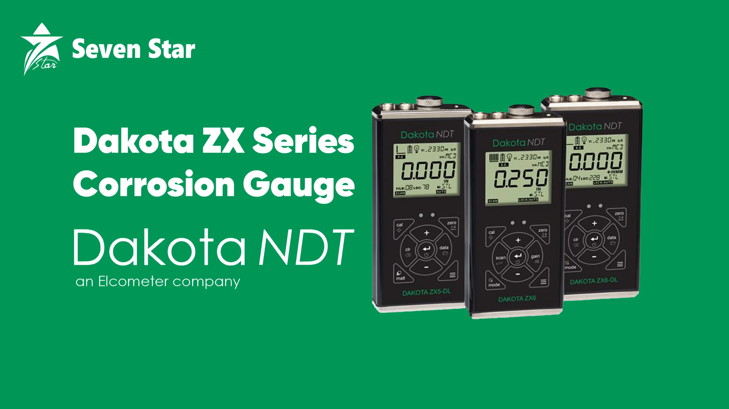
Wall thickness measurement deserves special attention because a corroded line can be thinner than the drawing suggests, and internal scale adds an unknown layer. Our corrosion thickness gauges category covers instruments that read through coatings, which helps when the pipe is painted.
Choosing the Mounting Mode: V, W or Z
The mounting mode defines how many times the beam crosses the pipe. More traverses give a longer acoustic path and a larger time difference, which helps on small pipes, but each reflection weakens the signal.
| Mode | Beam path | Typical use | Pros | Limitations |
|---|---|---|---|---|
| W (four traverses) | Three reflections off the pipe wall | Small pipes, roughly DN15–DN50 | Longest path, best resolution at low velocity | Weakest signal; poor on scaled or lined pipe |
| V (two traverses) | One reflection, transducers on the same side | Most medium pipes, roughly DN50–DN400 | Easy alignment with a single rail; cancels some cross-flow | Signal weakens on large or heavily scaled pipes |
| Z (one traverse) | Direct, transducers on opposite sides | Large pipes, attenuating fluids, scaled or lined pipe | Strongest signal | Harder to position accurately; needs access around the pipe |
The size ranges above are typical guidance only; manufacturers publish their own limits per transducer frequency. Many transmitters can also run two paths (for example two V paths in an X arrangement) to average out a distorted profile, which helps when straight run is short.
Transducer frequency should match the pipe. Higher-frequency transducers suit thin-walled small pipes; lower-frequency transducers penetrate thick walls, liners and large diameters. The transmitter calculates the spacing between transducers from the pipe data and selected mode, so any error in the inputs also misplaces the transducers.
Selecting the Location and Straight Run
Location rules for clamp-on meters are stricter than for many inline meters, because the transducers sample the profile along one or two lines rather than across the whole section.
- Straight run: a widely used guideline is at least 10 pipe diameters of straight pipe upstream and 5 downstream. After pumps, partly closed valves, two elbows in different planes or reducers, more is advisable, and manufacturers often publish specific values.
- Full pipe: choose a section that is always flooded. Vertical pipes with upward flow are ideal; avoid the top of a horizontal run and the downstream leg of a vertical drop.
- Orientation: on horizontal pipes, mount the transducers at the side, roughly within 45° of the horizontal plane, never at the top (air) or bottom (sediment).
- Avoid disturbances: keep away from welds, longitudinal seams, flanges and valves, and from points just downstream of pressure-reducing devices where cavitation can occur.
- Access: allow space for the clamping rail and for a technician to recheck the installation later.
If the available straight run is limited, placing the transducers further from the upstream disturbance than from the downstream one is the usual compromise. On large water mains, a two-path arrangement can recover much of the accuracy lost to an imperfect profile.
Surface Preparation and Coupling
The acoustic signal must cross from the transducer into the pipe wall with as little loss as possible.
- Remove loose paint, rust, scale and dirt over the transducer footprint. Firmly bonded paint is usually acceptable; flaking coatings are not.
- Avoid grinding deep flats, which change the wall thickness locally.
- Apply the couplant recommended by the manufacturer. Gel couplants suit temporary surveys; for permanent installations, solid coupling pads or long-life couplants are preferred because gels can dry out or wash away.
- Clamp the transducers with the supplied rail or straps at the correct torque; uneven pressure shifts the beam.
- On insulated pipes, cut back the insulation neatly and seal it afterwards so that water does not collect around the transducers.
Commissioning Checks That Reveal a Bad Installation
A stable flow reading proves very little. Before accepting the installation, review the transmitter diagnostics:
- Signal strength and signal quality: compare against the manufacturer’s acceptable range for the pipe size.
- Measured fluid sound speed: compare with the expected value for the fluid and temperature. A large difference usually means wrong pipe data or wrong spacing.
- Transit-time ratio or equivalent parameter, where available, which indicates whether the spacing is correct.
- Zero check: with a confirmed zero-flow condition (pump stopped and valve closed), check and adjust the zero.
- Comparison: if possible, compare with a reference such as a calibrated inline meter, a tank-level change over time or a pump curve.
Record all inputs and diagnostic values in the commissioning sheet. When the reading is challenged months later, this record makes troubleshooting much faster. A calibration program that includes these records, as described in our instrument calibration program guide, makes clamp-on results defensible.
Common Installation Errors
The same mistakes appear on survey after survey:
- Using the nominal pipe size instead of the measured outside diameter.
- Ignoring a cement or rubber lining, or entering the wrong lining thickness.
- Mounting at the top of a horizontal line where air collects.
- Installing a few diameters after a pump discharge or control valve.
- Leaving gel couplant on a hot outdoor pipe until it dries, causing intermittent signal loss.
- Entering the wrong pipe material, for example stainless instead of carbon steel, which changes the refraction angle.
- Measuring wall thickness at a different point from where the transducers are fixed.
- Clamping across a weld seam or onto heavy internal scale.
Hot, Dusty and Outdoor Sites in the GCC
Outdoor pipelines in Oman and the wider GCC add their own challenges. Pipe surfaces in direct sun can become far hotter than air temperature, so confirm both the transducer temperature rating and the couplant rating. Long-life coupling pads or high-temperature couplants are usually better than gel for permanent outdoor installations. A sunshade over the transmitter and transducers reduces thermal cycling and protects cables.
Dust and sand can work under clamping straps and into gel couplant during temporary surveys; clean thoroughly and protect the installation with a cover. For buried water mains, an inspection pit with drainage, a sealed transducer rated for submergence and cable protection are worth specifying. In desalination plants, seawater and brine lines are often GRP or lined steel, and the liner data must be correct for the meter to work at all.
Portable Survey or Permanent Clamp-On?
Portable meters are excellent for checking pump performance, auditing other meters and balancing water networks. Permanent clamp-on meters suit lines where cutting the pipe is impractical, such as large water mains and hazardous or high-pressure lines. For background on where non-invasive metering saves operating cost, see our article on reducing industrial OPEX with non-invasive flow meters. When the application requires the best possible accuracy, an inline ultrasonic or other spool-type meter calibrated in a flow lab remains the stronger option; the flow meter selection guide compares the alternatives.
Clamp-On Installation Checklist
- Outside diameter measured, not assumed
- Wall thickness measured at the mounting point
- Pipe material and liner type and thickness confirmed
- Fluid, temperature and expected sound speed recorded
- Mounting mode and transducer frequency matched to pipe size and condition
- Straight run of at least 10D upstream and 5D downstream, or the manufacturer’s value
- Transducers at the side of horizontal pipes, away from welds and seams
- Surface cleaned and correct couplant or pad used
- Signal strength, signal quality and measured sound speed within expected range
- Zero checked under confirmed no-flow conditions
- All inputs and diagnostics recorded in the commissioning sheet
Sourcing Clamp-On Flow Meters Through Seven Star LLC
Seven Star LLC supplies portable and permanent clamp-on ultrasonic meters, transducer sets, mounting rails and couplants on request, from manufacturers such as Siemens, Endress+Hauser, Krohne, Flexim and Panametrics. Browse the flowmeters category for typical models. We help with selection and with cross-checking part numbers; availability and lead time are confirmed at quotation.
Send us your pipe size, material, wall thickness, liner details and fluid data, or a photo of your existing transmitter nameplate, and we will prepare a quotation matched to your application.
Was this guide helpful?One click helps us write better guides for engineers.
Thank you! Glad it helped. Need this equipment for your project? Request a quotation
Thank you. We will use this to improve the guide.
Need a Quotation for Your Project?
Seven Star LLC supplies the industrial equipment covered in this article to customers across Oman and the GCC. Send us the part numbers, models or a short description with quantities, and our sales team will reply with a formal quotation.
- Genuine OEM products
- Supply across Oman & the GCC
- Formal quotation from our sales team
Free, no-obligation quotation · takes about 1 minute
Other enquiries: [email protected] · WhatsApp
More Blog





Frequently Asked Questions
A common guideline is at least 10 pipe diameters upstream and 5 diameters downstream of the transducers. After pumps, control valves or elbows in different planes, more straight run is advisable. Always check the manufacturer's installation manual, as some publish specific values per disturbance.
V mode suits most medium-sized pipes and is easier to install because both transducers sit on one rail on the same side. Z mode sends the beam across the pipe only once, giving a stronger signal on large, heavily scaled or lined pipes. W mode is generally used on small pipes where a longer path improves resolution.
Good signal strength does not prove correct pipe data. A wrong outside diameter, wall thickness, pipe material or ignored liner changes the calculated area and beam angle. Compare the measured fluid sound speed with the expected value; a large difference usually points to wrong inputs or transducer spacing.
Often yes, provided the liner is well bonded and its material and thickness are entered correctly in the transmitter. Lower-frequency transducers and Z mode usually perform better on lined pipes. Loose or cracked linings can block the signal completely.
Mount them on the side of the pipe, roughly within 45° of the horizontal plane. The top of the pipe can collect air and the bottom can collect sediment, both of which weaken or distort the signal. Also avoid welds, seams and flanges.
Gel couplant is fine for temporary surveys but can dry out, migrate or wash away over months, especially on hot outdoor pipes. Permanent installations usually use solid coupling pads or long-life couplants recommended by the manufacturer. Check the temperature rating against the actual pipe surface temperature.