
- Vibration Monitoring
- Industrial Communications
- PLC & I/O Cards
- Automation Accessories
- Controllers & Data Acquisition
- AC Drives
- Industrial Computers
- Encoders
- Safety Switches & Guard Locking
- Isolator & Barrier
- Automation Software
- HMI Displays
- Motor Soft Starters
- Servo Drives
- CCTV & Security
- Robotics
- Pneumatic Cylinders
- Machine Vision
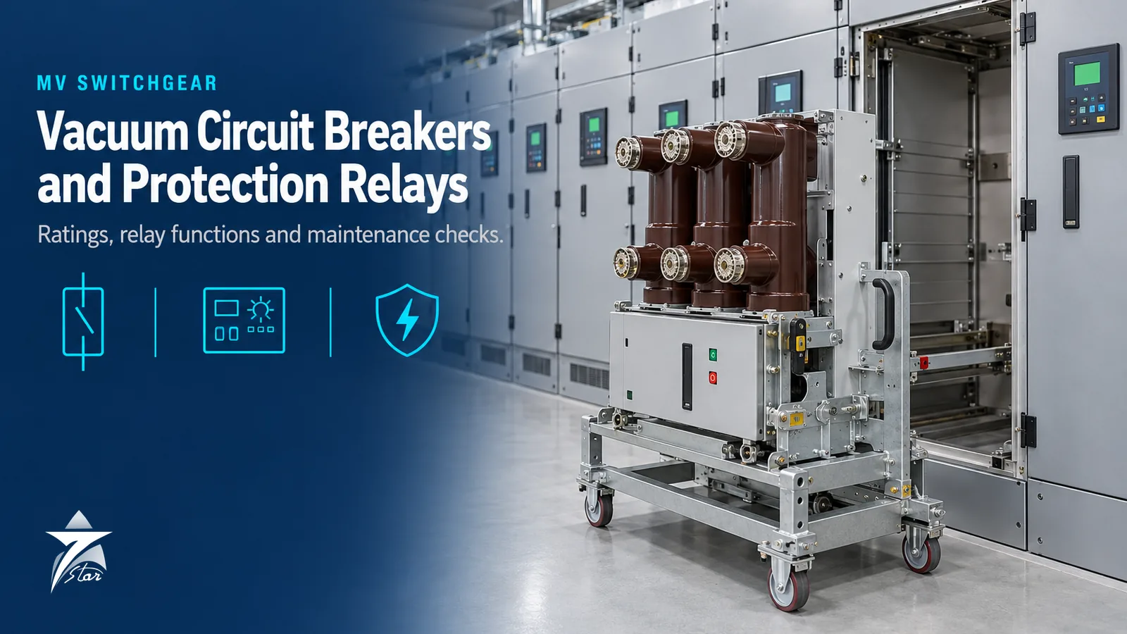
Medium-Voltage Vacuum Circuit Breakers and Protection Relays: Ratings, Selection, Maintenance and Retrofit
The vacuum circuit breaker is the standard switching device in medium-voltage distribution from roughly 3.3 kV to 36 kV, used on incomers, bus couplers, transformer feeders and motor feeders in refineries, gas plants, desalination plants and utility substations. A breaker is only as useful as the protection relay that tells it when to open, and both must be correctly rated, coordinated and maintained. When either is wrong, the result is a fault that is not cleared, a trip that takes out more of the plant than necessary, or a breaker that fails to interrupt at the moment it is needed.
This guide explains how vacuum interrupters work, how to read the ratings that matter, how to decode common type designations, which protection functions apply to which feeder, and what maintenance and retrofit work keeps the switchboard reliable in hot, dusty substations.
How a Vacuum Interrupter Works
When the contacts of a vacuum interrupter separate under load, the current continues to flow through an arc formed from metal vapour evaporated from the contact surfaces, typically a copper-chromium alloy. There is no gas to ionise, so the arc depends entirely on this vapour. At the natural current zero of the AC waveform, vapour production stops, the vapour condenses on the contacts and shield within microseconds, and the gap recovers its dielectric strength extremely quickly. This is why vacuum breakers interrupt reliably with a short contact gap and low operating energy.
Contact geometry is shaped (spiral or cup designs producing radial or axial magnetic fields) to keep the arc moving or diffuse so that erosion is spread evenly. Each interruption removes a small amount of contact material, and high fault currents remove much more. Manufacturers therefore provide a contact wear indicator or a measurement method, and they specify the number of rated short-circuit interruptions the interrupter can withstand. Because the interrupter is sealed, the main maintenance concerns shift from the arc chamber to the operating mechanism, the vacuum integrity and the insulation.
Ratings That Matter
IEC 62271-100 defines the ratings for AC circuit breakers above 1 kV, with common requirements in IEC 62271-1. The key values to check on any specification or nameplate are listed below.
| Rating | Typical MV values | What it means | Selection note |
|---|---|---|---|
| Rated voltage (Ur) | 7.2, 12, 17.5, 24 kV | Highest system voltage for which the breaker is designed | 12 kV class covers 11 kV systems common in Oman |
| Rated normal current (Ir) | 630, 1250, 2000, 2500, 3150, 4000 A | Continuous current within temperature-rise limits at rated ambient | Derate for ambient above 40 °C |
| Rated short-circuit breaking current (Isc) | 16, 20, 25, 31.5, 40 kA | Symmetrical RMS fault current the breaker can interrupt | Must exceed calculated maximum fault level at the bus |
| Rated short-circuit making current | 2.5 x Isc peak at 50 Hz | Peak current the breaker can close onto | Follows from breaking rating |
| Rated short-time withstand and duration | Equal to Isc for 1 s or 3 s | Current carried while closed until a downstream device clears | Check against relay clearing times |
| Rated operating sequence | O-0.3 s-CO-3 min-CO or O-3 min-CO-3 min-CO | Sequence of open and close-open operations the breaker can perform | The 0.3 s sequence is needed for rapid auto-reclose |
| Mechanical endurance class | M1 or M2 | M2 indicates extended mechanical endurance, 10,000 operations | M2 for frequently switched feeders such as motors |
| Electrical endurance class | E1 or E2 | E2 indicates extended electrical endurance | E2 for frequently switched or overhead line feeders |
Decoding ABB VD4/P designations
ABB VD4 breakers use a type code in which the numbers after the series name state rated voltage, rated normal current and rated breaking current. In the ABB VD4/P 12.06.32, 12 is 12 kV, 06 is 630 A and 32 is 31.5 kA. The same pattern gives:
| Type code | Rated voltage | Rated normal current | Rated breaking current | Typical application |
|---|---|---|---|---|
| VD4/P 12.06.32 | 12 kV | 630 A | 31.5 kA | Outgoing feeders, motor and transformer feeders |
| VD4/P 12.12.25 | 12 kV | 1250 A | 25 kA | Larger feeders on lower fault-level boards |
| VD4/P 12.12.40 | 12 kV | 1250 A | 40 kA | Feeders on high fault-level boards |
| VD4/P 12.20.40 | 12 kV | 2000 A | 40 kA | Incomers and bus sections |
| VD4/P 12.40.40 | 12 kV | 4000 A | 40 kA | Main incomers on large boards |
Pole centre distance, truck dimensions, auxiliary voltage, interlocking and the meaning of the suffix after the series name must be confirmed on the datasheet and against the switchgear panel, because a breaker with the correct electrical rating may still not rack into an existing cubicle.
Mechanism and accessories
Most MV vacuum breakers use a stored-energy spring mechanism charged by a motor, with a manual charging handle as backup. Specify the auxiliary supply voltage for the charging motor, closing coil and shunt trip coil, typically 110 V DC or 220 V DC from the substation battery. Other items to define are the number of auxiliary contacts, an undervoltage release if required, a second shunt trip coil for critical feeders, trip circuit supervision compatibility with the relay, and operation counters. For withdrawable breakers, confirm service, test and isolated positions and the interlocks between them and the earthing switch.
Withdrawable designs allow a faulty breaker to be replaced in minutes with a spare truck, which is why they dominate in process plants. Fixed breakers are cheaper and more compact but require the panel to be isolated for maintenance.
Protection Relays and Functions
The breaker interrupts; the relay decides. Modern numerical relays such as the ABB REF615 feeder protection relay combine multiple protection functions, measurement, event recording, disturbance recording and IEC 61850 communication in one device. Older installations commonly use earlier generation units such as the ABB REF542plus protection and control unit or the ABB SPAD34 transformer differential relay. Like-for-like spares keep existing schemes running, but settings and wiring must be checked on replacement.
| ANSI code | Function | Typical application |
|---|---|---|
| 50 / 51 | Instantaneous and time overcurrent | All feeders and incomers |
| 50N / 51N | Instantaneous and time earth fault | All feeders; sensitivity depends on earthing method |
| 67 / 67N | Directional overcurrent and earth fault | Parallel incomers, ring circuits |
| 87T | Transformer differential | Transformers typically above a few MVA |
| 87B | Busbar differential | Main switchboards with high fault levels |
| 46 | Negative sequence (phase unbalance) | Motors, generators |
| 49 | Thermal overload | Motors, cables, transformers |
| 27 / 59 | Undervoltage and overvoltage | Incomers, motor restart schemes |
| 81 | Frequency (over and under) | Load shedding, generator incomers |
| 79 | Auto-reclose | Overhead line feeders |
| 86 | Lockout relay | Hold breaker open after differential or other critical trip |
Coordination and CT selection
Relay coordination ensures that the device closest to the fault clears it first and upstream devices act only as backup. With numerical relays and vacuum breakers, a grading margin in the order of 0.25 to 0.4 s between successive stages is common practice, but the actual value should come from a documented coordination study using the real breaker opening times and relay tolerances.
Current transformers must be selected for the protection function. Protection classes such as 5P20 or 10P20 define composite error at an accuracy limit factor, while differential schemes often require class PX CTs specified by knee-point voltage, magnetising current and secondary resistance. Metering CTs (for example class 0.5) must not be used for protection because they saturate deliberately to protect meters. Check CT burden including lead resistance, especially on long cable runs to a remote relay panel.
Maintenance and Testing
Maintenance intervals depend on duty, environment and manufacturer instructions. The table below shows typical tasks; always follow the manufacturer’s manual for intervals and acceptance values.
| Task | Typical method | Typical interval | What it reveals |
|---|---|---|---|
| Visual inspection and cleaning | Inspect insulators, remove dust, check for tracking | Annually or more often in dusty sites | Contamination, tracking, overheating |
| Contact resistance | Micro-ohm meter with DC test current, commonly 100 A or more | Every major service | Contact wear, loose connections |
| Insulation resistance | Insulation tester, commonly 5 kV for 12 kV equipment | Every major service | Moisture, contamination, insulation degradation |
| Vacuum integrity | Power-frequency withstand across open contacts per manufacturer method | Per manufacturer, often every few years | Loss of vacuum in the interrupter |
| Timing and travel | Breaker analyser measuring open, close, pole discrepancy | Every major service | Mechanism wear, coil problems |
| Mechanism service | Lubrication with specified grease, spring and latch checks | Per operations count or time | Sluggish operation, failure to close or trip |
| Contact wear check | Wear indicator or measurement per manufacturer | After fault interruptions and at service | Remaining interrupter life |
| Relay secondary injection | Test set injecting current and voltage | Commissioning and periodic | Correct settings, logic and trip path |
Mechanism lubrication is the most neglected item. Grease hardens over years, particularly in hot rooms, and the most common failure mode of an MV breaker is not interruption failure but slow or failed operation of the mechanism.
Retrofit of old oil and SF6 breakers
Many older switchboards still use bulk-oil, minimum-oil or early SF6 breakers for which spares have become scarce. Options are a full switchboard replacement, a retrofit using a vacuum breaker on a purpose-designed truck that fits the existing cubicle, or a retrofill with a new breaker module into the old panel. Retrofit is usually faster and cheaper, but it needs type-test evidence for the combination, confirmation of the existing busbar short-circuit rating, and a review of interlocks, earthing switch operation and secondary wiring. Replacing electromechanical relays with numerical relays at the same time is common practice, and a new coordination study should be part of the work.
Considerations for Oman and the GCC
IEC 62271-1 normal service conditions assume a maximum ambient of 40 °C and a 24-hour average not above 35 °C. Substations in Oman can exceed this if HVAC fails or is undersized, so rated currents must be derated per manufacturer guidance or the cooling must be reliable. Treat switchgear room HVAC as a critical system with redundancy and alarms.
Fine dust ingress on insulation surfaces combined with coastal humidity at sites such as Sohar, Sur and Duqm can lead to tracking and flashover. Anti-condensation heaters must work, room pressurisation and filtration should be maintained, and cleaning frequency should be increased. Remote substations with long lead times for spares benefit from a spare breaker truck and spare relay held locally.
Common Mistakes
- Selecting breaking capacity from the transformer rating instead of a fault study that includes motor contribution and future grid changes.
- Ordering a replacement breaker by electrical rating only and finding that it does not fit the cubicle or interlocks.
- Using metering CTs or undersized protection CTs for differential protection.
- Never lubricating the mechanism because the interrupter is sealed and considered maintenance-free.
- Replacing a relay like-for-like without verifying settings files and firmware compatibility.
Vacuum Circuit Breaker and Relay Procurement Checklist
- Rated voltage, normal current, breaking current and short-time withstand duration confirmed against the fault study
- Operating sequence and endurance classes (M2, E2) specified for the duty
- Fixed or withdrawable, with truck dimensions and pole centres matched to the panel
- Auxiliary voltage for motor, closing coil and trip coils confirmed
- Auxiliary contacts, undervoltage release and second trip coil requirements listed
- Relay functions, communication protocol and CT inputs defined
- CT class, ratio and burden verified for each protection function
- Ambient temperature derating and switchgear room HVAC reviewed
- Spares for coils, charging motor and relay identified for remote sites
Sourcing Breakers and Relays Through Seven Star LLC
Seven Star LLC supplies and sources medium-voltage breakers, protection relays and related spares for utilities, industrial plants and contractors in Oman and the GCC. Browse the circuit breaker category and the ABB brand page. Include the full nameplate data, panel type and any existing relay order code with your enquiry. For related power-system topics, see our guides to VFD selection in hot climates and UPS power protection.
Send your breaker nameplate data or relay order codes to Seven Star LLC through our contact page for a quotation.
Was this guide helpful?One click helps us write better guides for engineers.
Thank you! Glad it helped. Need this equipment for your project? Request a quotation
Thank you. We will use this to improve the guide.
Need a Quotation for Your Project?
Seven Star LLC supplies the industrial equipment covered in this article to customers across Oman and the GCC. Send us the part numbers, models or a short description with quantities, and our sales team will reply with a formal quotation.
- Genuine OEM products
- Supply across Oman & the GCC
- Formal quotation from our sales team
Free, no-obligation quotation · takes about 1 minute
Other enquiries: [email protected] · WhatsApp
More Blog





Frequently Asked Questions
When the contacts separate, the current flows through an arc of metal vapour from the contact surfaces. At the natural current zero the vapour condenses almost instantly and the vacuum gap recovers its dielectric strength, so the current is not re-established. This allows a small contact gap and low operating energy.
In ABB VD4 type codes the numbers indicate rated voltage, rated normal current and rated breaking current. VD4 12.06.32 therefore means 12 kV, 630 A and 31.5 kA. Mechanical dimensions, auxiliary voltage and accessories must still be confirmed on the datasheet.
The usual field method is a power-frequency or DC high-voltage withstand test across the open contacts using the voltage and duration specified by the breaker manufacturer. A loss of vacuum causes breakdown at a much lower voltage. Some test sets use magnetron methods to estimate internal pressure more precisely.
IEC 62271-100 defines mechanical endurance classes. Class M1 is the standard level, while class M2 indicates extended mechanical endurance of 10,000 operations. M2 breakers are preferred for frequently switched feeders such as motors and capacitor banks.
Intervals depend on the manufacturer, number of operations, fault interruptions and environment. Many operators perform visual inspection annually and a major service with timing, contact resistance and insulation tests every few years. Dusty or humid sites usually need shorter intervals.
A typical radial feeder uses phase overcurrent (50/51) and earth fault (50N/51N) protection. Transformer feeders often add differential protection (87T), motor feeders add thermal overload (49) and negative sequence (46), and incomers may add directional, voltage and frequency functions. The final selection should come from the protection philosophy and coordination study.