
- Vibration Monitoring
- Industrial Communications
- PLC & I/O Cards
- Automation Accessories
- Controllers & Data Acquisition
- AC Drives
- Industrial Computers
- Encoders
- Safety Switches & Guard Locking
- Isolator & Barrier
- Automation Software
- HMI Displays
- CCTV & Security
- Motor Soft Starters
- Servo Drives
- Robotics
- Pneumatic Cylinders
- Machine Vision
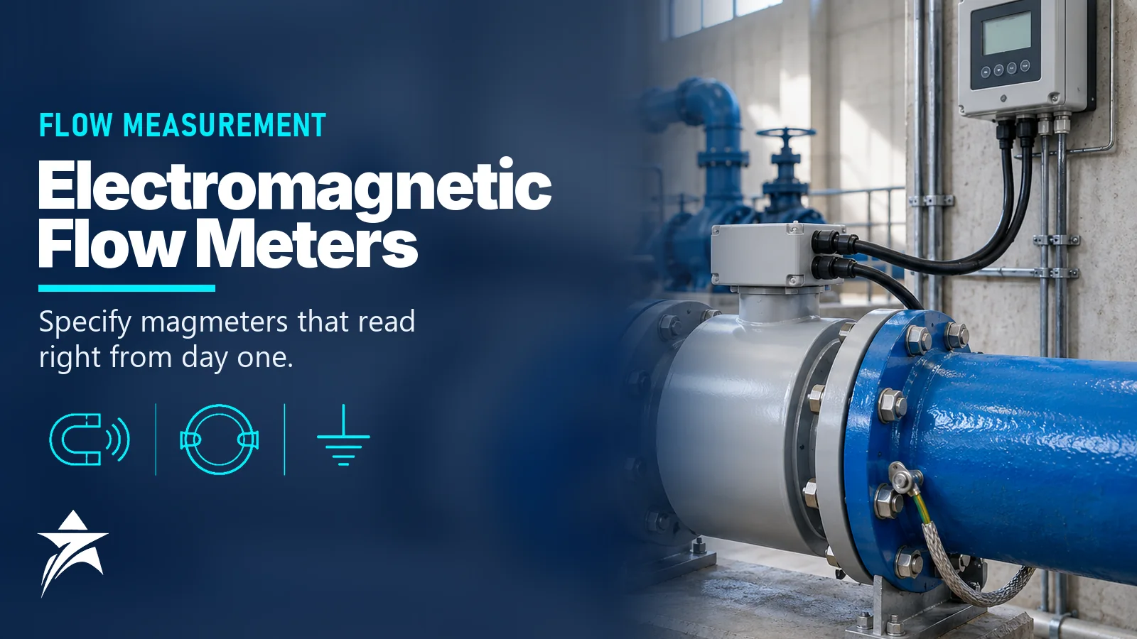
Electromagnetic Flow Meter Guide: Liner and Electrode Selection, Conductivity, Grounding and Installation
An electromagnetic flow meter (magmeter) is the default choice for conductive liquids such as raw water, seawater, sewage, slurries and many chemicals, because it has no moving parts, no obstruction in the bore and practically no pressure loss. Yet a large share of magmeter complaints in the field have nothing to do with the meter itself: they come from the wrong liner, an electrode metal that pits in chloride service, a fluid below the conductivity limit, or poor grounding on a lined or plastic pipe. This guide explains how the meter works and then walks through liner and electrode selection, conductivity limits, grounding, installation and troubleshooting, so that the datasheet you send for quotation describes a meter that will actually work in your line.
How an Electromagnetic Flow Meter Works
The measuring principle is Faraday’s law of induction. Coils on the flow tube create a magnetic field across the pipe. A conductive liquid moving through that field behaves like a moving conductor, so a small voltage is induced between two electrodes mounted at right angles to both the field and the flow direction. The induced voltage is proportional to the magnetic flux density, the distance between electrodes (the internal diameter) and the average flow velocity. Because field strength and diameter are fixed by design, the signal is a direct measure of mean velocity, and the transmitter multiplies velocity by the bore area to give volumetric flow.
Several practical consequences follow from this principle:
- The output is volumetric and largely independent of density, viscosity, pressure and temperature, as long as the liquid is conductive enough and the pipe is full.
- The signal is tiny, typically in the microvolt to millivolt range, so electrical noise, stray currents and electrode coating matter more than mechanical wear.
- Gases, steam and hydrocarbons such as crude oil, diesel or condensate cannot be measured: they are not conductive.
Most modern meters use pulsed DC excitation, switching the coil current at a low frequency so that the transmitter can sample the signal after the field has settled and subtract electrochemical offsets at the electrodes. For slurries and pulp, which create spiky noise, some manufacturers offer higher-frequency or dual-frequency excitation.
Conductivity Limits and What Happens Below Them
The liquid must carry the induced voltage to the electrodes. Many general-purpose magmeters specify a minimum conductivity of about 5 µS/cm, and a number of models are rated down to roughly 1 µS/cm or lower in specific sizes or with special electrode designs. Capacitive (non-contacting electrode) designs can work on even lower conductivity, but they are specialised instruments.
Typical reference values help in screening:
- Potable and raw water: usually well above the limit, commonly a few hundred µS/cm.
- Seawater and desalination brine: very high, tens of thousands of µS/cm.
- RO permeate, demineralised water and boiler feedwater: often near or below 1 µS/cm and frequently unsuitable for a standard magmeter.
- Hydrocarbons, solvents and many oils: effectively non-conductive.
Conductivity also falls with temperature and changes with process conditions, so check the lowest value the line will see, not the average. If your plant runs RO or demineralisation, the permeate side normally needs a different technology such as Coriolis or ultrasonic; our water quality analyzer guide for desalination and wastewater gives useful context on the conductivity levels involved. Below the limit, the reading becomes noisy, drifts or collapses towards zero even with flow present.
Liner Selection: Matching the Bore to the Fluid
The liner insulates the liquid from the metal tube so that the induced voltage is not short-circuited. It is also the part that faces the chemistry, temperature, abrasion and vacuum of the process. The table below summarises common options; exact limits differ by manufacturer and by whether the transmitter is compact or remote, so always confirm on the model datasheet.
| Liner | Typical strengths | Watch-outs | Common applications |
|---|---|---|---|
| Hard rubber (ebonite) | Low cost, good for large diameters, good general water resistance | Limited temperature range, typically below about 80–90 °C; not for strong oxidisers or hydrocarbons | Potable water, raw water, seawater, irrigation, cooling water |
| Soft rubber | Good abrasion resistance | Low temperature limit; chemical resistance narrower than fluoropolymers | Slurries, sand-laden water, mining tailings |
| Polyurethane | Very good abrasion resistance | Low temperature limit; not for hot water or many chemicals | Abrasive slurries, dredging, ash water |
| PTFE | Broad chemical resistance, wide temperature range | Can deform or collapse under vacuum unless reinforced; cold flow at flanges | Acids, alkalis, chemical dosing, hot water |
| PFA | Chemical resistance similar to PTFE, smoother and more resistant to deposits; often moulded with a reinforcing grid for vacuum resistance | Higher cost | Aggressive chemicals, food and pharma, lines with vacuum risk |
| ETFE | Good chemical and abrasion balance | Lower temperature limit than PFA | Chemical service with some solids |
| Ceramic | Hard, dimensionally stable, abrasion resistant | Sensitive to thermal shock and mechanical impact | Small sizes, abrasive or high-purity service |
Two points are often missed: a pump trip or steam-out followed by cooling can pull vacuum and collapse an unsupported PTFE liner, and steam cleaning usually rules out rubber and polyurethane liners.
Electrode Materials and Designs
Electrodes are wetted, small and electrically critical. A pitted or coated electrode changes the signal long before anything else in the meter fails.
- 316L stainless steel: standard for water and wastewater, but vulnerable to pitting and crevice corrosion in high-chloride service.
- Hastelloy C (nickel alloy): a common upgrade for seawater, brine and many chloride-bearing chemicals.
- Titanium: good in seawater and oxidising chloride environments; not suitable for some reducing acids.
- Tantalum: excellent resistance to hydrochloric acid and most strong acids, but attacked by hydrofluoric acid and strong alkalis.
- Platinum (or platinum-iridium): very wide chemical resistance, used where nothing else survives, including hydrofluoric acid service.
Beyond material, look at the electrode style. Bullet-nose or self-cleaning electrode shapes reduce fouling in sewage and sludge. Some meters offer electrode cleaning by applying a short voltage pulse, or electrode impedance diagnostics that warn of coating before the reading drifts. A third electrode or a pair of ground electrodes may also be included, and an empty-pipe detection electrode at the top of the bore is common on water meters.
Grounding and Potential Equalisation
A magmeter measures a voltage relative to the liquid, so the liquid must be at the same potential as the meter’s reference. On a bare metal pipe this is usually achieved by bonding the sensor flanges to the adjacent pipe flanges. On lined steel, GRP, HDPE or PVC pipe, the pipe does not contact the liquid, so a different path is needed:
- Grounding rings (earthing discs) between the meter and the pipe flanges on both sides, in a material compatible with the fluid, bonded to the meter body.
- A built-in reference or grounding electrode, which some manufacturers allow in place of rings for certain sizes and fluids.
- A bonding conductor from the meter to a clean plant earth, kept short and separate from motor and VFD earths where possible.
Pipelines with cathodic protection need special care. The meter must not short out the protection system, so manufacturers specify isolated installations with insulated bolts and a dedicated bonding arrangement. Lines near large variable-speed drives, electrolysis cells or welding activity can also carry stray currents that appear as a noisy or offset reading. In such cases, follow the manufacturer’s grounding drawing exactly and verify it with a resistance check rather than relying on the flange bolts.
Installation Rules That Protect Accuracy
The flow profile, a full pipe and a stable signal path are the three installation requirements.
- Straight runs: a common baseline is about 5 pipe diameters upstream and 2 downstream of the electrode plane, measured from elbows, tees, reducers and valves. Some manufacturers accept shorter runs or specify longer ones after pumps and partly open valves; follow the model manual.
- Full pipe: on horizontal lines, avoid the highest point of the system where air collects; a low section or a slight U-arrangement keeps the tube flooded. Vertical lines with upward flow are preferred.
- Electrode orientation: mount the meter so that the electrode axis is close to horizontal. Electrodes at 12 o’clock see air bubbles; at 6 o’clock they collect sediment.
- Control valves and pump suction: put control valves downstream of the meter where possible, and never place a meter on a pump suction where vacuum and cavitation are likely.
- Gaskets: centre them carefully; a gasket protruding into the bore disturbs the profile and can damage soft liners.
- Remote transmitter: in high ambient temperature or where the sensor sits in a pit or chamber, a remote-mounted transmitter with an IP68 sensor and potted junction box is often more reliable than a compact unit.
Velocity also matters. Many magmeters are specified over roughly 0.3 to 10 m/s, but the best accuracy and least fouling are usually achieved in the range of about 1 to 3 m/s. Reducing the meter one size below the line is common in water networks to raise velocity; the small extra pressure loss across the reducers is usually acceptable.
Sizing and Specification Data to Collect
A complete enquiry avoids rework at quotation stage. Before asking for a quote, collect:
- Fluid name, conductivity (minimum), solids content and whether it is abrasive or fouling.
- Minimum, normal and maximum flow, and line size and schedule or pipe material.
- Operating and design pressure and temperature, including any cleaning or vacuum conditions.
- Flange standard and rating, for example ASME B16.5 Class 150 or EN 1092-1 PN16, and face-to-face length if replacing an existing meter.
- Liner, electrode and grounding-ring preferences, or the corrosion data needed to choose them.
- Power supply, outputs (4–20 mA with HART, pulse, Modbus or other fieldbus) and display needs.
- Compact or remote transmitter, cable length, and IP or submergence rating.
- Hazardous-area classification if relevant, which our hazardous area classification guide explains in detail.
GCC Conditions: Seawater, Heat and Buried Sensors
Plants in Oman and the wider GCC push magmeters harder than many temperate sites. Seawater intakes and brine lines call for hard rubber, PFA or PTFE liners combined with Hastelloy C or titanium electrodes; 316L electrodes in these services tend to pit. Flanged meters on outdoor lines can see surface temperatures well above ambient in direct sun, so a sunshade over the transmitter and a remote electronics option are worth considering when the sensor sits on an exposed rack.
Water distribution networks often install meters in underground chambers that flood. In these cases, specify a sensor rated for permanent submergence, a remote transmitter in a ventilated kiosk and cable glands suited to the environment. For remote sites without mains power, battery-powered magmeters designed for water networks are an option, although their sampling rate and outputs differ from line-powered units. Sewage and treated effluent lines in the region also carry grit and grease, which favour self-cleaning electrodes and periodic inspection.
Common Mistakes and Troubleshooting
Most magmeter faults trace back to a short list of causes:
- Reading drifts or is noisy at zero flow: check grounding first, then electrode coating, then whether the pipe is actually full.
- Reading too low with sudden steps: suspect partial filling or entrained air; review the installation height and upstream air release.
- Reading lost after a chemical change: verify that conductivity has not dropped below the meter’s limit.
- Gradual over-reading or under-reading: look for build-up on the liner that reduces the effective bore, or electrode coating changing the signal.
- Damaged liner after a trip: investigate vacuum events and liner type.
- Empty-pipe alarm with a full pipe: the detection electrode may be coated or the detection threshold may need adjustment.
Built-in verification functions that check coils, electrodes and electronics against factory baselines do not replace a wet calibration, but they help to justify longer calibration intervals within a documented program, as described in our instrument calibration program guide.
When a Magmeter Is the Wrong Choice
A magmeter is not a universal answer. For non-conductive liquids, mass-based custody measurement of hydrocarbons or very low-conductivity water, other technologies fit better. Coriolis, ultrasonic, vortex and positive displacement meters all have their place; our overview on how to choose the right flow meter compares them by fluid and duty, and the flowmeters category lists the main types.
Magmeter Specification Checklist
- Conductivity confirmed above the meter’s minimum at worst-case conditions
- Liner selected for chemistry, temperature, abrasion and vacuum
- Electrode material checked against chlorides and acids in the fluid
- Grounding method defined for the actual pipe material and any cathodic protection
- Straight run and full-pipe conditions confirmed on the piping drawing
- Velocity checked at minimum and maximum flow, with a size reduction considered
- Compact or remote electronics chosen for ambient temperature and access
- Outputs, power supply, IP rating and hazardous-area marking listed
- Flange standard and face-to-face length matched to the existing piping
Sourcing Electromagnetic Flow Meters Through Seven Star LLC
Seven Star LLC supplies electromagnetic flow meters, spare transmitters, grounding rings and related metering system components on request from manufacturers such as Endress+Hauser, Krohne, Siemens, ABB, Yokogawa and Emerson. We help with selection and with cross-checking model codes against existing installations; availability and lead time are confirmed at quotation.
Planning a new magmeter or replacing an existing one? Send us the process datasheet, the old meter’s nameplate photo or your RFQ, and we will return a matched quotation for your line.
Was this guide helpful?One click helps us write better guides for engineers.
Thank you! Glad it helped. Need this equipment for your project? Request a quotation
Thank you. We will use this to improve the guide.
Need a Quotation for Your Project?
Seven Star LLC supplies the industrial equipment covered in this article to customers across Oman and the GCC. Send us the part numbers, models or a short description with quantities, and our sales team will reply with a formal quotation.
- Genuine OEM products
- Supply across Oman & the GCC
- Formal quotation from our sales team
Free, no-obligation quotation · takes about 1 minute
Other enquiries: [email protected] · WhatsApp
More Blog




Frequently Asked Questions
Many general-purpose magmeters specify a minimum of about 5 µS/cm, and some models are rated down to around 1 µS/cm or lower in certain sizes. Special capacitive-electrode designs can go lower still. Always check the minimum conductivity the process will reach, because conductivity changes with temperature and process conditions.
No for hydrocarbons, because they are not electrically conductive. Demineralised water, RO permeate and boiler feedwater are often below the conductivity limit of standard magmeters. For these fluids, Coriolis, ultrasonic, turbine or positive displacement meters are usually considered instead.
316L stainless steel electrodes are prone to pitting in high-chloride water, so Hastelloy C or titanium electrodes are commonly selected for seawater and brine. Combine them with a liner suited to the temperature, such as hard rubber, PTFE or PFA. Confirm the final choice against the manufacturer's corrosion table.
Grounding rings are normally needed when the adjacent pipe is lined, plastic or otherwise does not contact the liquid electrically. They give the liquid a defined reference potential at both sides of the sensor. On bare metal pipe, bonding straps to the pipe flanges may be enough, and some meters offer a built-in grounding electrode instead.
A common baseline is about 5 pipe diameters upstream and 2 diameters downstream of the electrode plane. Pumps, partly open valves and multiple elbows may require more, and some manufacturers allow less. The model installation manual is the final reference.
The usual causes are poor grounding, stray electrical currents, a partially filled pipe or coated electrodes. Check the bonding path and the earth connections first, then confirm the tube is full and inspect the electrodes. Many transmitters also offer a low-flow cutoff and diagnostics that help isolate the cause.