


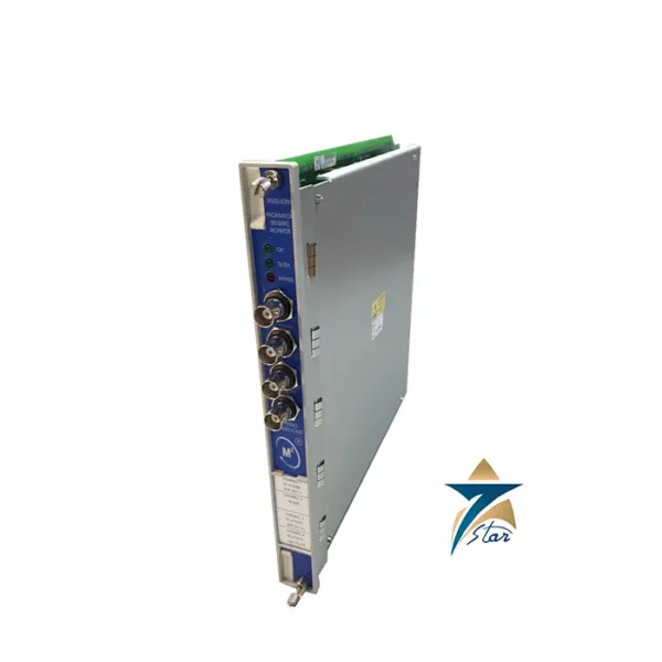
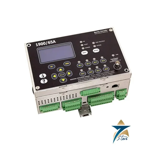
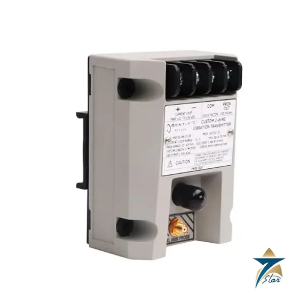
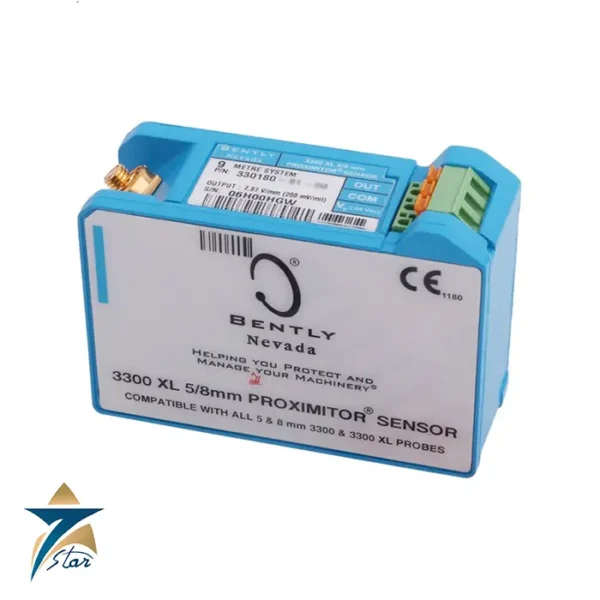
Related products


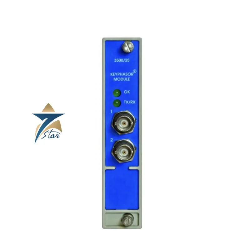
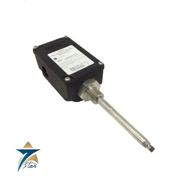
The Bently Nevada 3500/25 Keyphasor® Module provides the precise once-per-revolution phase and speed reference that unlocks advanced diagnostics in a Bently Nevada 3500 rack. By conditioning proximity-probe or magnetic-pickup tach signals into a clean Keyphasor reference, the 3500/25 enables order tracking, orbit/polar plots, startup/coast-down analysis, and accurate correlation of alarms across the rack—without interfering with protection logic. Deployed alongside vibration monitors such as 3500/40M (Proximitor) or 3500/42M (Velocity/Accel), and streamed via a 3500/22M TDI to System 1, the Keyphasor module turns raw vibration into actionable, phase-aware insight for compressors, turbines, large motors/generators, pumps and fans.
A machinery protection rack can alarm on overall levels, but fault identification (unbalance, misalignment, rubs, looseness, fluid-induced instabilities, blade-pass, gear mesh) often requires knowing phase vs. speed. The 3500/25 Keyphasor Module delivers a stable one-per-rev (or scaled) reference so you can:
Track phase angle of shaft vibration, create orbits and polar plots, and separate synchronous from asynchronous content.
Run order-based diagnostics during startups, coast-downs and variable-speed operation.
Align alarms and events from multiple monitors in time and rotational position for fast root-cause analysis.
Inputs & Transducers: Accepts eddy-current proximity (tach) or magnetic pickup signals. Each input is validated, shaped and converted to a Keyphasor pulse train.
Dual Independent Channels: Two channels can be configured redundant (two sensors on one machine), diverse (two different machines), or gear-scaled (tooth count) for multi-target applications.
Scaling & Validation: Supports once-per-rev (keyway/notch) or gear-ratio scaling to derive true RPM. Signal validation maintains clean triggering across low and high speeds.
Rack Integration: The Keyphasor reference is distributed to other 3500 monitors for protection and to System 1 (via 3500/22M TDI) for trends, waveforms, orbits and order plots. Protection remains in the monitors; the 3500/25 supplies the reference only.
When your rack includes a 3500/22M TDI, the 3500/25 provides synchronized phase/speed data so System 1 can store phase-referenced waveforms, build Bode/Cascade/Waterfall plots, and correlate temperature, process and vibration events by rotational position. This gives maintenance teams higher confidence during balancing, alignment checks, and post-trip investigations.
Single Train (Redundant Tach): CH-A once-per-rev proximity on keyway; CH-B magnetic pickup on gear tooth—redundancy plus cross-validation.
Twin-Train Machine: CH-A on Compressor-1; CH-B on Compressor-2—single module serving two shafts.
High-Tooth Gears: Gear with N teeth; configure pulses/rev to 1 using scaling so monitors and System 1 see accurate RPM.
Keyphasor + Keyphasor (Dual Bearings): Use two once-per-rev targets for complex trains needing multiple phase references.
Transducer data: type (prox/mpu), gap, sensitivity, cable length.
Targeting method: once-per-rev notch/keyway or gear tooth count (N).
Speed range: min/max RPM for reliable triggering and anti-bounce filtering.
Channel use: redundant vs. separate machines; assign scaling per channel.
Rack map: confirm slot, monitor dependencies (e.g., 40M/42M), and System 1/TDI versions.
Validation: live check RPM stability vs. DCS/PLC tach; verify phase coherence with radial probes.
Turbomachinery: gas/steam turbines, expanders—order plots, Bode during run-ups; phase-based rub/misalignment detection.
Compressors & Blowers: unbalance, looseness, aerodynamic instabilities, surge event timing.
Large Motors/Generators: soft-foot/misalignment identification with phase tracking.
Pumps/Fans: phase-referenced trend correlation for cavitation/rub.
Place the once-per-rev mark at a clear mechanical reference (keyway or precision notch).
For gears, document exact tooth count and desired pulses/rev; apply gear scaling accordingly.
Route tach leads away from high-noise power cabling; check grounding/shielding.
After configuration, run a startup test: verify stable RPM, correct phase lock, and expected order amplitudes in System 1.
Keep a spare 3500/25 for fleets where run-up data are critical to outage planning.
Share your transducer type/model, gap and cable length, tooth count or notch details, machine speed range, rack BOM/slot map, and System 1/TDI versions. We’ll confirm firmware compatibility, channel assignments, and the right scaling so your 3500/25 Keyphasor Module delivers a clean, reliable reference across the rack.
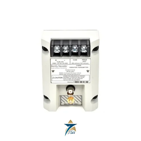
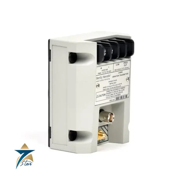
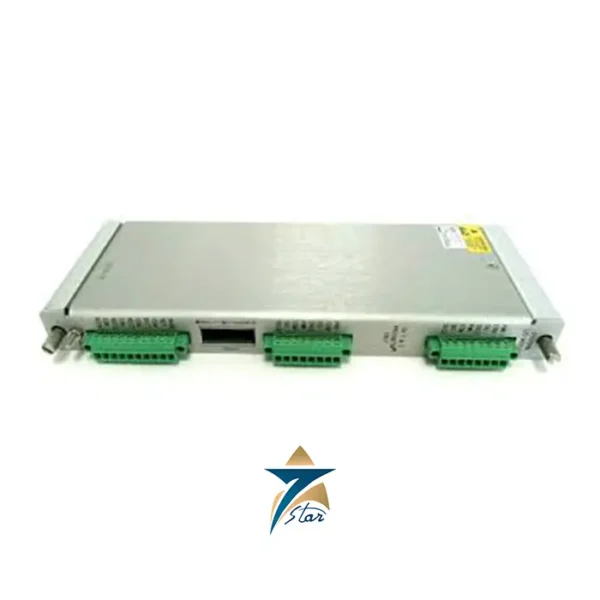
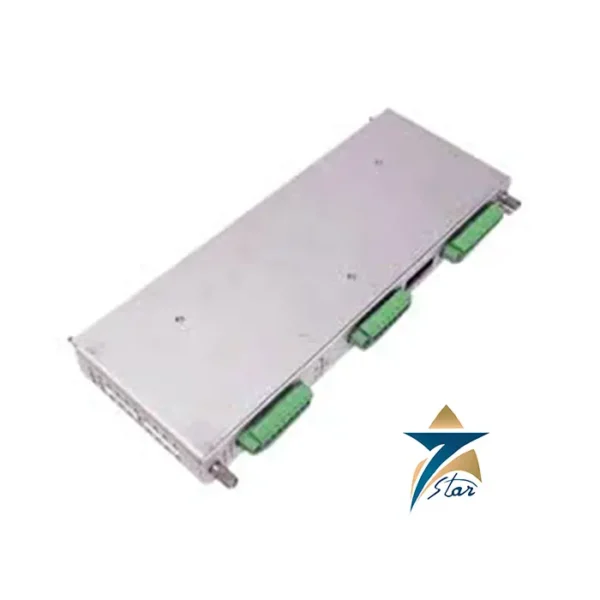
Included: 3500/25 Keyphasor® Module (card only).
Not included: transducers, I/O modules, rack hardware, cables—quoted as required.
Vibration category: https://omansevenstar.com/product-category/automation/vibration/
3500/22M TDI: /product/bently-nevada-3500-22m-tdi/
3500/40M Proximitor: /product/bently-nevada-3500-40m-proximitor-monitor/
3500/60 Temperature: /product/bently-nevada-3500-60-temperature-monitor/
Need help setting once-per-rev or gear scaling? Send your tach probe details, tooth count and rack BOM. Seven Star LLC will validate configuration, confirm availability/lead time, and offer the best regional pricing for Bently Nevada 3500/25 Keyphasor® Module spares and upgrades.
Bently Nevada, a division of Baker Hughes, is a global leader in asset condition monitoring and protection technologies. For over six decades, the company has set the industry standard in machinery diagnostics, vibration analysis, and predictive maintenance solutions.
Its advanced systems and sensors are designed to ensure maximum equipment uptime, safety, and efficiency across power generation, oil & gas, and industrial manufacturing sectors. From vibration probes and monitoring racks to software platforms like System 1, Bently Nevada products enable real-time insight and data-driven decision-making.
Seven Star LLC supplies genuine Bently Nevada equipment, sensors, and monitoring solutions to clients across the Middle East, providing trusted reliability, expert support, and seamless integration for modern industrial operations.

Reviews
There are no reviews yet.